
Decoupling capacitor


In electronics, a decoupling capacitor is a capacitor used to decouple (i.e. prevent electrical energy from transferring to) one part of a circuit from another. Noise caused by other circuit elements is shunted through the capacitor, reducing its effect on the rest of the circuit. For higher frequencies, an alternative name is bypass capacitor as it is used to bypass the power supply or other high-impedance component of a circuit.
Discussion[edit]
Active devices of an electronic system (e.g. transistors, integrated circuits, vacuum tubes) are connected to their power supplies through conductors with finite resistance and inductance. If the current drawn by an active device changes, the voltage drop from the power supply to the device will also change due to these impedances. If several active devices share a common path to the power supply, changes in the current drawn by one element may produce voltage changes large enough to affect the operation of others – voltage spikes or ground bounce, for example – so the change of state of one device is coupled to others through the common impedance to the power supply. A decoupling capacitor provides a bypass path for transient currents, instead of flowing through the common impedance. [1]
The decoupling capacitor works as the device’s local energy storage. The capacitor is placed between the power line and the ground to the circuit the current is to be provided. According to the capacitor current–voltage relation

a voltage drop between power line and ground results in current draw out from the capacitor to the circuit. When capacitance C is large enough, sufficient current is supplied to maintain an acceptable range of voltage drop. The capacitor stores a small amount of energy that can compensate for the voltage drop in the power supply conductors to the capacitor. To reduce undesired parasitic effective series inductance, small and large capacitors are often placed in parallel, adjacent to individual integrated circuits (see Decoupling capacitor § Placement).
In digital circuits, decoupling capacitors also help prevent radiation of electromagnetic interference from relatively long circuit traces due to rapidly changing power supply currents.
Decoupling capacitors alone may not suffice in such cases as a high-power amplifier stage with a low-level pre-amplifier coupled to it. Care must be taken in layout of circuit conductors so that heavy current at one stage does not produce power supply voltage drops that affect other stages. This may require re-routing printed circuit board traces to segregate circuits, or the use of a ground plane to improve stability of power supply.
Decoupling[edit]


A bypass capacitor is often used to decouple a subcircuit from AC signals or voltage spikes on a power supply or other line. A bypass capacitor can shunt energy from those signals, or transients, past the subcircuit to be decoupled, right to the return path. For a power supply line, a bypass capacitor from the supply voltage line to the power supply return (neutral) would be used.
High frequencies and transient currents can flow through a capacitor to circuit ground instead of to the harder path of the decoupled circuit, but DC cannot go through the capacitor and continues on to the decoupled circuit.
Another kind of decoupling is stopping a portion of a circuit from being affected by switching that occurs in another portion of the circuit. Switching in subcircuit A may cause fluctuations in the power supply or other electrical lines, but you do not want subcircuit B, which has nothing to do with that switching, to be affected. A decoupling capacitor can decouple subcircuits A and B so that B doesn't see any effects of the switching.
Switching subcircuits[edit]
In a subcircuit, switching will change the load current drawn from the source. Typical power supply lines show inherent inductance, which results in a slower response to change in current. The supply voltage will drop across these parasitic inductances for as long as the switching event occurs. This transient voltage drop would be seen by other loads as well if the inductance between two loads is much lower compared to the inductance between the loads and the output of the power supply.
To decouple other subcircuits from the effect of the sudden current demand, a decoupling capacitor can be placed in parallel with the subcircuit, across its supply voltage lines. When switching occurs in the subcircuit, the capacitor supplies the transient current. Ideally, by the time the capacitor runs out of charge, the switching event has finished, so that the load can draw full current at normal voltage from the power supply and the capacitor can recharge. The best way to reduce switching noise is to design a PCB as a giant capacitor by sandwiching the power and ground planes across a dielectric material.[citation needed]
Sometimes parallel combinations of capacitors are used to improve response. This is because real capacitors have parasitic inductance, which causes the impedance to deviate from that of an ideal capacitor at higher frequencies.[2]
Transient load decoupling[edit]
Transient load decoupling as described above is needed when there is a large load that gets switched quickly. The parasitic inductance in every (decoupling) capacitor may limit the suitable capacity and influence appropriate type if switching occurs very fast.
Logic circuits tend to do sudden switching (an ideal logic circuit would switch from low voltage to high voltage instantaneously, with no middle voltage ever observable). So logic circuit boards often have a decoupling capacitor close to each logic IC connected from each power supply connection to a nearby ground. These capacitors decouple every IC from every other IC in terms of supply voltage dips.
These capacitors are often placed at each power source as well as at each analog component in order to ensure that the supplies are as steady as possible. Otherwise, an analog component with poor power supply rejection ratio (PSRR) will copy fluctuations in the power supply onto its output.
In these applications, the decoupling capacitors are often called bypass capacitors to indicate that they provide an alternate path for high-frequency signals that would otherwise cause the normally steady supply voltage to change. Those components that require quick injections of current can bypass the power supply by receiving the current from the nearby capacitor. Hence, the slower power supply connection is used to charge these capacitors, and the capacitors actually provide the large quantities of high-availability current.
Placement[edit]
A transient load decoupling capacitor is placed as close as possible to the device requiring the decoupled signal. This minimizes the amount of line inductance and series resistance between the decoupling capacitor and the device. The longer the conductor between the capacitor and the device, the more inductance is present.[3]
Since capacitors differ in their high-frequency characteristics, decoupling ideally involves the use of a combination of capacitors. For example in logic circuits, a common arrangement is ~100 nF ceramic per logic IC (multiple ones for complex ICs), combined with electrolytic or tantalum capacitor(s) up to a few hundred μF per board or board section.
Example uses[edit]
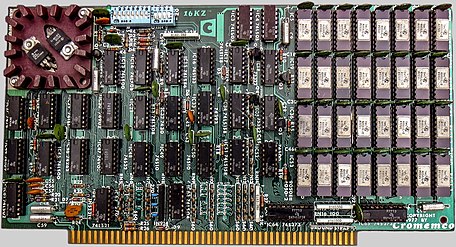
These photos show old printed circuit boards with through-hole capacitors, where as modern boards typically have tiny surface-mount capacitors.
-
 1980s Commodore 64 main board. Most of the "orange" round disc parts are decoupling capacitors.
 -

-
-
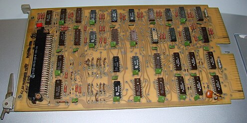 1970s I1 parallel interface board for Electronika 60. The green rectangular parts are decoupling capacitors.


See also[edit]
- Ceramic capacitor
- Equivalent series inductance
- Equivalent series resistance
- Film capacitor
- E-series of preferred numbers
References[edit]
- ^ Don Lancaster, TTL Cookbook', Howard W. Sams, 1975, no ISBN, pp.23-24
- ^ "Using Decoupling Capacitors". Cypress. 2017-04-07. Retrieved 2018-08-12.
- ^ Capacitor Design Data, and Decoupling Placement, How-to on Leroy's Engineering Web Site
External links[edit]
- Choosing and Using Bypass Capacitors – application note from Intersil
- Decoupling – decoupling guide for various frequencies by Henry W. Ott
- Power Supply Noise Reduction – how to design effective supply bypassing and decoupling networks by Ken Kundert
- ESR and Bypass Capacitor Self Resonant Behavior: How to Select Bypass Caps – article written by Douglas Brooks
- Circuit Board Decoupling Information – decoupling guidelines for various types of circuit boards
- Basic Principles of Signal Integrity – Altera whitepaper
- Bypass Capacitors, an Interview With Todd Hubing – by Douglas Brooks