
File:PWM, 3-level.svg

Size of this PNG preview of this SVG file: 688 × 475 pixels. Other resolutions: 320 × 221 pixels | 640 × 442 pixels | 1,024 × 707 pixels | 1,280 × 884 pixels | 2,560 × 1,767 pixels.
Original file (SVG file, nominally 688 × 475 pixels, file size: 18 KB)
| This is a file from the Wikimedia Commons. Information from its description page there is shown below. Commons is a freely licensed media file repository. You can help. |
Summary
| Description |
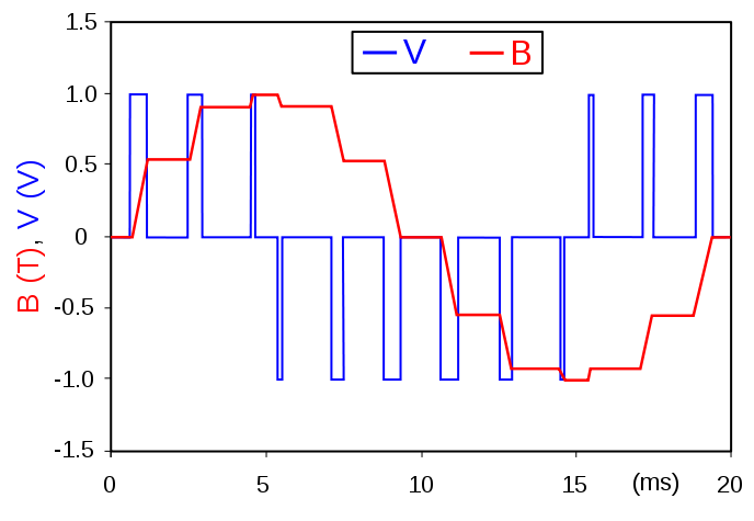
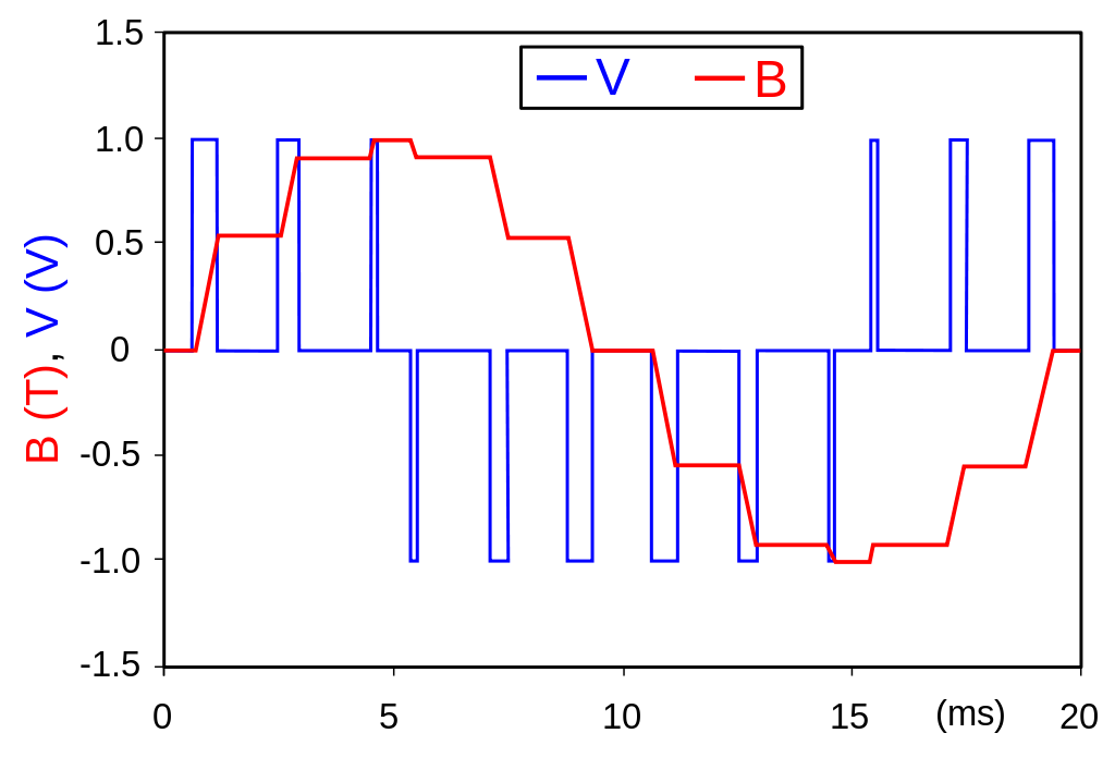
English: A simplified example of pulse-width modulated (PWM) voltage supply to a magnetic circuit. The voltage (blue waveform) in a magnetic circuit is proportional to the rate of change of the flux density (red waveform). Therefore, by using PWM supply the resultant flux density can be controlled with relative ease. This method is commonly used for supplying electric motors, in which the torque is proportional to the flux density. As can be seen, with a series of appropriately modulated voltage impulses the resultant flux density can be modulated to be close to desired sinusoidal waveform. In the example shown (for 50 Hz), for clarity the switching frequency is 600 Hz, in real devices the switching frequency is much higher - even up to 10 kHz or higher. Of course, for higher fundamental frequency the switching frequencies would be even higher.
Polski: Przykładowe przedstawienie modulacji szerokości impulsu (PWM) dla obwodu magnetycznego. Napięcie elektryczne (niebieski przebieg) w obwodzie magnetycznym jest proporcjonalne do szybkości zmian indukcji magnetycznej (czerwony przebieg). Dlatego też, poprzez użycie PWM wypadkowa indukcja magnetyczna może być kształtowana z względną łatwością. Metoda ta jest szeroko stosowana do zasilania i kontrolowania pracy silników elektrycznych, w których moment obrotowy na wale silnika jest proporcjonalny do indukcji magnetycznej. Jak widać na rysunku, wypadkowa indukcja (dąży się zazwyczaj do kształtu sinusoidalnego) może być łatwo kształtowana poprzez użycie odpowiednio modulowanych impulsów. W pokazanym przykładzie (dla 50 Hz), dla jasności rysunku użyto częstotliwość przełączania 600 Hz. W rzeczywistości jednak stosuje się znacznie większe częstotliwości przełączania - nawet do 10 kHz lub więcej. Oczywiście dla nośnych częstotliwości wyższych niż 50 Hz częstotliwości przełączania będą znacznie większe. |
| Date | |
| Source | Own work |
| Author | Zureks |
| SVG development |
Licensing
I, the copyright holder of this work, hereby publish it under the following licenses:

|
Permission is granted to copy, distribute and/or modify this document under the terms of the GNU Free Documentation License, Version 1.2 or any later version published by the Free Software Foundation; with no Invariant Sections, no Front-Cover Texts, and no Back-Cover Texts. A copy of the license is included in the section entitled GNU Free Documentation License. |
| This file is licensed under the Creative Commons Attribution-Share Alike 3.0 Unported license. | ||
| ||
| This licensing tag was added to this file as part of the GFDL licensing update. |
This file is licensed under the Creative Commons Attribution-Share Alike 2.5 Generic, 2.0 Generic and 1.0 Generic license.
- You are free:
- to share – to copy, distribute and transmit the work
- to remix – to adapt the work
- Under the following conditions:
- attribution – You must give appropriate credit, provide a link to the license, and indicate if changes were made. You may do so in any reasonable manner, but not in any way that suggests the licensor endorses you or your use.
- share alike – If you remix, transform, or build upon the material, you must distribute your contributions under the same or compatible license as the original.
You may select the license of your choice.
File history
Click on a date/time to view the file as it appeared at that time.
| Date/Time | Thumbnail | Dimensions | User | Comment | |
|---|---|---|---|---|---|
| current | 20:36, 24 March 2007 | | 688 × 475 (18 KB) | Zureks | {{Information |Description=An example of pulse-width modulated voltage supply to a magnetic circuit. The voltage (blue waveform) in a magnetic circuit is proportional to the rate of change of the flux density (red waveform). Therefore, by using PWM suppl |
File usage
The following pages on the English Wikipedia use this file (pages on other projects are not listed):
Global file usage
The following other wikis use this file:
- Usage on ca.wikipedia.org
- Usage on da.wikipedia.org
- Usage on et.wikipedia.org
- Usage on fa.wikipedia.org
- Usage on fr.wikipedia.org
- Usage on hi.wikipedia.org
- Usage on hu.wikipedia.org
- Usage on ja.wikipedia.org
- Usage on lv.wikipedia.org
- Usage on pl.wikipedia.org
- Usage on ru.wikipedia.org
- Usage on sl.wikipedia.org
- Usage on sv.wikipedia.org
- Usage on uk.wikipedia.org
- Usage on vi.wikipedia.org
- Usage on zh.wikipedia.org