
File:Recepteur tube limaille.JPG

Size of this preview: 600 × 599 pixels. Other resolutions: 240 × 240 pixels | 481 × 480 pixels | 947 × 946 pixels.
Original file (947 × 946 pixels, file size: 87 KB, MIME type: image/jpeg)
| This is a file from the Wikimedia Commons. Information from its description page there is shown below. Commons is a freely licensed media file repository. You can help. |
Summary
| Description |
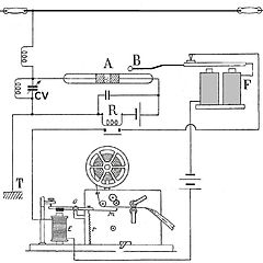
Français : Récepteur cohéreur enregistreur à tube de limaille (de Branly) 1902. Ce récepteur d'ondes hertziennes a permis de réaliser les premières liaisons radios à grande distance en radiotélégraphie. En 1902 : depuis le phare du Stiff, essais par Camille Tissot de la station Ouessant TSF avec un récepteur radio à cohéreur et un émetteur à arc à deux boules. Cette station à une portée radiotélégraphiques de 80 kilomètres avec une flotte de 14 navires en mer et avec Brest.
Français : Principe: Le tube A est en série dans-le circuit d'un élément de pile de 1,5 V et dans le circuit d'un relais sensible (généralement un relais magnétique) R. Une onde arrive, le tube devient conducteur, la palette du relais en R ce fermer un contact établissant un second circuit. Ce circuit contient: le Morse inscripteur E et un électro-aimant F, dit frappeur, cet électro-aimant mis en action attire sa palette, qui porte une sphère B, laquelle vient frapper légèrement le tube à limaille et le décohère par choc. Dès lors, revenu à son état primitif, le cohéreur est dé nouveau apte à recueillir une autre onde, qui s'inscrira à la suite de la première sur la bande du Morse.
Deutsch: RX Fritter
English: Early radio receiver circuit using a "Branly coherer", a tube containing metal filings, as a detector. This type of receiver, used until about 1906, made possible the first long distance radio telegraphy communication.
In 1902: since the headlight of Stiff, tests by Camille Tissot of the station Ushant TSF with a radio operator receiver with coherer and an arc transmitter with two balls. This station with a range radio telegraphy of 80 kilometers with a fleet of 14 ships at sea and with . The radio waves from the antenna at top are applied through a resonant circuit consisting of a coil and tuning capacitor (CV) to the coherer (A). The coherer tube is in a series circuit with a 1.5V battery and a sensitive relay (R). When a radio wave arrives, the tube becomes conducting, and the relay closes a contact in a second circuit which contains a Morse paper tape recorder (E) and an electromagnet "decoherer" or "trembler" (F). The recorder registers the signal on the tape, while the arm of the electromagnet (B) lightly taps the coherer. This disturbs the metal filings, returning the coherer to its nonconducting state so it is prepared to detect the next radio symbol. In actual operation, if the radio signal is still present when the decoherer taps the tube, the coherer immediately turns on again, causing another tap. The result is a continuous tapping or "trembling" of the electromagnet arm during the duration of each incoming Morse code symbol. |
| Date | |
| Source | Own work |
| Author | F1jmm |
Licensing
I, the copyright holder of this work, hereby publish it under the following licenses:

|
Permission is granted to copy, distribute and/or modify this document under the terms of the GNU Free Documentation License, Version 1.2 or any later version published by the Free Software Foundation; with no Invariant Sections, no Front-Cover Texts, and no Back-Cover Texts. A copy of the license is included in the section entitled GNU Free Documentation License. |
This file is licensed under the Creative Commons Attribution-Share Alike 3.0 Unported, 2.5 Generic, 2.0 Generic and 1.0 Generic license.
- You are free:
- to share – to copy, distribute and transmit the work
- to remix – to adapt the work
- Under the following conditions:
- attribution – You must give appropriate credit, provide a link to the license, and indicate if changes were made. You may do so in any reasonable manner, but not in any way that suggests the licensor endorses you or your use.
- share alike – If you remix, transform, or build upon the material, you must distribute your contributions under the same or compatible license as the original.
You may select the license of your choice.

|
This circuit image could be re-created using vector graphics as an SVG file. This has several advantages; see Commons:Media for cleanup for more information. If an SVG form of this image is available, please upload it and afterwards replace this template with
{{vector version available|new image name}}.
It is recommended to name the SVG file “Recepteur tube limaille.svg”—then the template Vector version available (or Vva) does not need the new image name parameter. |


File history
Click on a date/time to view the file as it appeared at that time.
| Date/Time | Thumbnail | Dimensions | User | Comment | |
|---|---|---|---|---|---|
| current | 05:15, 30 July 2010 | | 947 × 946 (87 KB) | F1jmm | ffu phare |
| 15:22, 15 September 2009 |  | 947 × 946 (99 KB) | F1jmm | faible impédance | |
| 14:40, 14 March 2009 |  | 986 × 954 (105 KB) | F1jmm | {{Information |Description= {{fr| Récepteur cohéreur enregistreur à tube de limaille (de Branly) 1902 }} |Source=travail personnel (own work) |Date=15 Mars 2009 |Author=F1jmm |Permission= |other_versions=1 }} <!--{{ImageUpload|basic}}-- |
File usage
The following pages on the English Wikipedia use this file (pages on other projects are not listed):
Global file usage
The following other wikis use this file:
- Usage on eo.wikipedia.org
- Usage on fr.wikipedia.org
- Usage on hr.wikipedia.org
- Usage on pl.wikipedia.org