Multistage interconnection networks (MINs) are a class of high-speed computer networks usually composed of processing elements (PEs) on one end of the network and memory elements (MEs) on the other end, connected by switching elements (SEs). The switching elements themselves are usually connected to each other in stages, hence the name.
MINs are typically used in high-performance or parallel computing as a low-latency interconnection (as opposed to traditional packet switching networks), though they could be implemented on top of a packet switching network. Though the network is typically used for routing purposes, it could also be used as a co-processor to the actual processors for such uses as sorting; cyclic shifting, as in a perfect shuffle network; and bitonic sorting.
Interconnection network are used to connect nodes, where nodes can be a single processor or group of processors, to other nodes.
Interconnection networks can be categorized on the basis of their topology. Topology is the pattern in which one node is connected to other nodes.
There are two main types of topology: static and dynamic.
Static interconnect networks are hard-wired and cannot change their configurations. A regular static interconnect is mainly used in small networks made up of loosely couple nodes. The regular structure signifies that the nodes are arranged in specific shape and the shape is maintained throughout the networks.
Some examples of static regular interconnections are:[1][2]
Completely connected network Completely connected networkIn a mesh network, multiple nodes are connected with each other. Each node in the network is connected to every other node in the network. This arrangement allows proper communication of the data between the nodes. But, there are a lot of communication overheads due to the increased number of node connections.
Shared busShared bus networkThis network topology involves connection of the nodes with each other over a bus. Every node communicates with every other node using the bus. The bus utility ensures that no data is sent to the wrong node. But, the bus traffic is an important parameter which can affect the system.
RingRing NetworkThis is one of the simplest ways of connecting nodes with each other. The nodes are connected with each other to form a ring. For a node to communicate with some other node, it has to send the messages to its neighbor. Therefore, the data message passes through a series of other nodes before reaching the destination. This involves increased latency in the system.
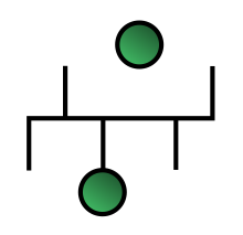
TreeTree networkThis topology involves connection of the nodes to form a tree. The nodes are connected to form clusters and the clusters are in-turn connected to form the tree. This methodology causes increased complexity in the network.
Hypercube 4*4 HypercubeThis topology consists of connections of the nodes to form cubes. The nodes are also connected to the nodes on the other cubes.
ButterflyButterfly NetworkThis is one of the most complex connections of the nodes. As the figure suggests, there are nodes which are connected and arranged in terms of their ranks. They are arranged in the form of a matrix.
In dynamic interconnect networks, the nodes are interconnected via an array of simple switching elements.[3] This interconnection can then be changed by use of routing algorithms, such that the path from one node to other nodes can be varied. Dynamic interconnections can be classified as:
In crossbar switch, there is a dedicated path from one processor to other processors. Thus, if there are n inputs and m outputs, we will need n*m switches to realize a crossbar.
As number of outputs increase, number of switches increases by factor of n. For large network this will be a problem.
Crossbar network
An alternative to this scheme is staged switching.
In a single stage interconnect network, the input nodes are connected to output via a single stage of switches.
The figure shows 8*8 single stage switch using shuffle exchange.
8x8 Single stage network
As one can see, from a single shuffle, not all input can reach all output. Multiple shuffles are required for all inputs to be connected to all the outputs.
A multistage interconnect network is formed by cascading multiple single stage switches. The switches can then use their own routing algorithm or controlled by a centralized router, to form a completely interconnected network.
Multistage Interconnect Network can be classified into three types:[4]
Non-blocking: A non-blocking network can connect any idle input to any idle output, regardless of the connections already established across the network. Crossbar is an example of this type of network.
Rearrangeable non-blocking: This type of network can establish all possible connections between inputs and outputs by rearranging its existing connections.
Blocking: This type of network cannot realize all possible connections between inputs and outputs. This is because a connection between one free input to another free output is blocked by an existing connection in network.
The number of switching elements required to realize a non-blocking network in highest, followed by rearrangeable non-blocking. Blocking network uses least switching elements.
An Omega network consists of multiple stages of 2*2 switching elements. Each input has a dedicated connection to an output. An N*N omega network has log(N) number of stages and N/2 number of switching elements in each stage for perfect shuffle between stages. Thus network has complexity of 0(N log(N)). Each switching element can employ its own switching algorithm. Consider an 8*8 omega network. There are 8! = 40320 1-to-1 mappings from input to output. There are 12 switching element for total permutation of 2^12 = 4096. Thus, it is a blocking network.
A Clos network uses 3 stages to switch from N inputs to N outputs. In the first stage, there are r= N/n crossbar switches and each switch is of size n*m. In the second stage there are m switches of size r*r and finally the last stage is mirror of first stage with r switches of size m*n. A clos network will be completely non-blocking if m >= 2n-1. The number of connections, though more than omega network is much less than that of a crossbar network.
A Beneš network is a rearrangeably non-blocking network derived from the clos network by initializing n = m = 2. There are (2log(N) - 1) stages, with each stage containing N/2 2*2 crossbar switches. An 8*8 Beneš network has 5 stages of switching elements, and each stage has 4 switching elements. The center three stages has two 4*4 benes network. The 4*4 Beneš network, can connect any input to any output recursively.
^Solihin, Yan (2009). Fundamentals of Parallel Computer Architecture. USA: OmniPress. ISBN978-0-9841630-0-7.
^Blake, J. T.; Trivedi, K. S. (1989-11-01). "Multistage interconnection network reliability". IEEE Transactions on Computers. 38 (11): 1600–1604. doi:10.1109/12.42134. ISSN0018-9340.