
Metal-mesh optical filter
Metal-mesh optical filters are optical filters made from stacks of metal meshes and dielectric. They are used as part of an optical path to filter the incoming light to allow frequencies of interest to pass while reflecting other frequencies of light.
Metal-mesh filters have many applications for use in the far infrared (FIR)[1] and submillimeter regions of the electromagnetic spectrum. These filters have been used in FIR and submillimeter astronomical instruments for over 4 decades,[2] in which they serve two main purposes: band-pass or low-pass filters are cooled and used to lower the noise equivalent power of cryogenic bolometers (detectors) by blocking excess thermal radiation outside of the frequency band of observation,[3] and band-pass filters can be used to define the observation band of the detectors. Metal-mesh filters can also be designed for use at 45° to split an incoming optical signal into several observation paths, or for use as a polarizing half-wave plate.[4]
Transmission line theory can be applied to metallic meshes to understand how they work and the overall light transmission properties of groups of metallic meshes grouped together.[5] Modeling the properties of these metallic meshes allows for reliable manufacture of filters with the desired transmission properties.
Theory[edit]

In 1967 Ulrich showed that the optical transmission properties of a metallic mesh can be modeled by considering the mesh to be a simple circuit element on a free space transmission line. To develop the theory of metallic meshes, he focused on the properties of two types of mesh structure: a metallic grid with square openings; and a grid of metallic squares supported on a thin dielectric substrate. Using the transmission line method, he then modeled the behavior of each of these meshes as either lumped inductance (square openings) or a lumped capacitance (free-standing squares). These two types of meshes are commonly referred to as inductive or capacitive meshes.[2][5]
The theory developed by Ulrich to explain light transmission by metallic meshes makes a few assumptions and idealizations, which will be used here as well in explaining the theory. This theory is valid for thin meshes, i.e. , but the following equations assume that the grid is infinitely thin, the metallic parts are perfectly conducting, and the supporting dielectric film in the capacitive grids has no effect. The electromagnetic theory can then be applied to develop a model of an oscillating circuit on a transmission line model that explains the transmission properties of these meshes quite well as long as the wavelength of light is larger than the size of the metallic element ().[5]


Electromagnetic theory[edit]
Electromagnetic theory of light can be used to describe how light incident on both capacitive and inductive metallic meshes will behave in transmission, reflection, and absorption.
Transmission and reflection[edit]
If an incident plane wave of electromagnetic radiation hits a metallic grid of either type perpendicular to its path it will scatter, and the only propagating parts will be the zeroth order reflected wave and the zeroth order transmitted wave.[5] The frequency of both of these electric fields will be equal, and the ratio of their amplitudes is , where is the reflection coefficient, and is the normalized frequency. If we assume that the incident wave had unit amplitude, we can add the incident wave to the transmitted scattered wave to get the total amplitude of the transmitted wave, :


.
![{\displaystyle \tau (\omega )=\left[1+\Gamma (\omega )\right]}](https://wikimedia.org/api/rest_v1/media/math/render/svg/d7a3f6f0107f7c59a0acc3263dbeb6946c5e6876)
Since we are neglecting losses, the amplitude squared of the reflected and transmitted waves must equal unity:
.

Given these two relations, the phase of the reflection coefficient, , and the phase of the transmission coefficient can be simply related to the transmitted power, , which can be directly measured in experiments with metallic meshes.


Solving these equations lets us find the amplitude of the scattered wave in terms of the phases of the reflected and transmitted waves:
.

The result of drawing vs. in the complex plane is a unit half circle centered on the point which is in the upper half-plane for inductive grids and in the lower half-plane for capacitive grids. At all frequencies the transmitted and reflected waves are out of phase .[5]

![{\displaystyle \left[Re(-1/2),Im(0)\right]}](https://wikimedia.org/api/rest_v1/media/math/render/svg/add7475960d6d9ef33ce06fdb4cf9df10d7c8dbd)


Until now, the theory has been general—whether the mesh was inductive or capacitive has not been specified. Since and are independent of polarization, we can apply Babinet's principle to the capacitive and inductive grids. Concisely, Babinet's principle states that if we swap the metallic parts of a grid for the gaps, (i.e., make a complementary mesh), then the sum of the transmitted wave from the original structure and the structure's complement must equal the original incident wave.[6] Therefore, if we have complementary capacitive and inductive grids,
.
![{\displaystyle \left[\tau _{ind}+\tau _{cap}\right]=1}](https://wikimedia.org/api/rest_v1/media/math/render/svg/f0dc1203412455f5f310bcf158885772939af98f)
Given the relations between the reflected and transmitted waves found earlier, this means that the transmitted wave in an inductive grid is equal to the negative of the reflected wave in a capacitive grid and vice versa, and also that the transmitted powers for capacitive and inductive grids sum to unity for a unit incident wave.


.[5]

Solving for the exact form of or requires solving Maxwell's equations on the grids, which for the general case can only be solved numerically. However, in an inductive grid the metal is continuous, and hence DC currents can exist. Considering the limiting case of , the inductive grid must reflect the entire incident wave[5] because of the boundary conditions for the electric field at the surface of a conductor.[7] The relations derived above therefore show that a capacitive mesh will transmit the entire incident wave in this case.


Because the grids are complements of each other, these equations show that a capacitive mesh is a low-pass filter and an inductive mesh is a high-pass filter.[5]
Absorption[edit]
Up until now, the theory has only been considering the ideal case where the grids are infinitely thin and perfectly conducting. In principle grids with finite dimensions could also absorb some of the incident radiation either through ohmic losses or losses in the dielectric supporting material.
Assuming that the skin depth of the metal being used in the grids is much smaller than the thickness of the grid, the real part of the surface impedance of the metal is where is the conductivity of the metal and is the skin depth of the metal. With a reflected wave , the change in the magnetic field amplitude across the grid is because of surface currents on both sides of the grid. The average surface currents on both sides of the grid are .[5]


Given the average surface current and the surface impedance, we could calculate the power dissipated as . However, because the actual extent of the metal in the grids is different between the capacitive and inductive grids and a flat sheet of metal, we need to introduce a factor which is the ratio of the area the grid to that of a flat sheet. For capacitive grids, and for inductive grids . This modifies the power dissipated to be . Using the definition of skin depth, the unitless absorptivity, where is the incident power, of the grid is


.[5]

For microwave and infrared radiation incident on copper, this unitless absorptivity comes out to be to , which means that the initial assumption that absorption could be ignored in this ideal model was a good one. The dielectric losses can likewise be ignored.[5]


Comparison to measurements[edit]
For single layer metallic grids, the simple theory Ulrich laid out works quite well. The functions and can be determined by measuring the transmission through the filter, and the phases and can be measured by setting two identical grids variable distances apart and measuring the interference maximum of as a function of separation. Measurements of very thin nearly ideal grids show the expected behavior and have very low absorptive loss.[5]


In order to build filters out of metallic meshes with the desired properties, it is necessary to stack many metallic meshes together, and while the simple electromagnetic theory laid out above works well for one grid, it becomes more complicated when more than one element is introduced. However, these filters can be modeled as elements in a transmission line, which has easily calculable transmission properties.[2][5]
Transmission line model[edit]
A transmission line model of metallic meshes is easy to work with, flexible, and is readily adapted for use in electronic modeling software. It not only handles the case of a single metallic grid, but is easily extended to many stacked grids.
Theoretical model[edit]

Under the conditions of normal incidence and the electric field across a metallic grid is continuous, but the magnetic field is not,[6] so a transmission line with an admittance between the two lines can be used to model the transmission and reflection from a metallic filter. If, for example, three identical grids were stacked, then there would be three admittance shunts in parallel across the transmission line. Using simple transmission line theory, the reflection coefficient and transmission coefficient are calculated to be


which of course satisfy the original relation between the transmission and reflection coefficients:
.
In a lossless circuit, the admittance becomes a purely imaginary susceptance, where is a real function of . Because of the complementary nature of the grids, we also know that .[5]


To calculate the behavior of an ideal metallic grid, only needs to be found. The standard approach is not to characterize the equivalent circuit by , but instead to parameterize it with values of , , and which duplicate the transmission properties of the filters. At low frequencies, a reasonable model is to replace the shunt in the transmission line with a capacitor of value for capacitive meshes and an inductor of value for inductive meshes, where for complementary grids . However, at high frequencies this model fails to reflect the behavior of real metallic meshes correctly. The measured transmissions as are


.[5]

The behavior of the transmission in the two limiting cases can be replicated with the transmission line model by adding an extra element. In addition, losses can be taken into account by adding another resistance . At resonance , the impedance of capacitors and inductors are . Typically, and have to be measured based on transmission properties of the grids, and both depend on the parameter . The included in the 2-element equivalent circuit is consistent with the earlier calculation of absorptivity, which gives . The following table summarizes all the parameters to go from equivalent circuit parameters to expected reflection and transmission coefficients.[5]


| Capacitive circuit | Inductive Circuit | |
|---|---|---|
| Normalized Impedance | ||
| Generalized frequency | ||
| Normalized admittance | ||
| Reflectivity | ||
| Transmissivity | ||
| Reflected phase | ||
| Transmitted phase | ||
| Absorptivity | ||


The real power in this model is it allows prediction of the transmission properties of many metallic grids stacked together with spacers to form interference filters. Stacks of capacitive grids make a low-pass filter with a sharp frequency cutoff above which transmission is almost zero. Likewise, stacks of inductive grids make a high-pass filter with a sharp frequency cutoff below which transmission is almost zero. Stacked inductive and capacitive meshes can be used to make band-pass filters.[2]
Comparison to measurements[edit]
The transmission line model gives the expected first-order transmission of the stacked metal mesh filters; however, it cannot be used to model transmission of light that is incident at an angle, loss in the supporting dielectric materials, or the transmission properties when due to diffraction. To model those effects, scientists have used a cascade scattering matrix approach to model dielectric loss, and other modeling tools such as High Frequency Structure Simulator and Floquet mode analysis.[2]

Manufacture[edit]
The manufacture of metal-mesh filters starts with photolithography of copper on a substrate, which allows fine control over the parameters , , and . The metallic grids are made of thin copper film on top of a dielectric substrate such as mylar or polypropylene. The copper is thick, and the dielectric ranges from to .[2]


There are two ways to create a multi-layer metal-mesh filter. The first is to suspend the separate layers in supporting rings with a small gap which is either filled with air or under vacuum between the layers. However, these filters are mechanically delicate. The other way to build a multi-layer filer is to stack sheets of dielectric between the layers of metallic mesh and hot press the whole stack together. This results in a filter that is one solid piece. Hot pressed filters are mechanically robust and when impedance matched to vacuum show a pass-band fringe due to Fabry-Perot interference in the underlying dielectric material.[2]
Use in experiments[edit]
These filters have been used in FIR and submillimeter astronomical instruments for over 4 decades,[2] in which they serve two main purposes: band-pass or low-pass filters are cooled and used to lower the noise equivalent power of cryogenic bolometers by blocking excess thermal radiation outside of the frequency band of observation,[3] and band-pass filters can be used to define the observation band of the detectors. Metal-mesh filters can also be designed for use at 45° to split an incoming optical signal into several observation paths, or for use as a polarizing half-wave plate.[4]
-
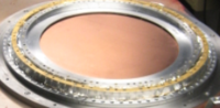 Low-pass filter at 4 Kelvin used for blocking excess thermal radiation installed in the South Pole Telescope receiver.
 -
 Low-pass metal-mesh filters at 250mK used to define the upper edge of the detector observation band in the South Pole Telescope receiver.


References[edit]
- ^ Arline M. Melo; Mariano A. Kornberg; Pierre Kaufmann; Maria H. Piazzetta; et al. (Nov 2008). "Metal mesh resonant filters for terahertz frequencies". Applied Optics. 47 (32): 6064–9. Bibcode:2008ApOpt..47.6064M. doi:10.1364/AO.47.006064. PMID 19002231.
- ^ a b c d e f g h Ade, Peter A. R.; Pisano, Giampaolo; Tucker, Carole; Weaver, Samuel (Jul 2006). Zmuidzinas, Jonas; Holland, Wayne S; Withington, Stafford; Duncan, William D (eds.). "A Review of Metal Mesh Filters" (PDF). Millimeter and Submillimeter Detectors and Instrumentation for Astronomy III. Proceedings of the SPIE. Millimeter and Submillimeter Detectors and Instrumentation for Astronomy III. 6275: 62750U. Bibcode:2006SPIE.6275E..0UA. doi:10.1117/12.673162. S2CID 7647444.
- ^ a b D. W. Porterfield; J. L. Hesler; R. Densing; E. R. Mueller; et al. (Sep 1994). "Resonant metal-mesh bandpass filters for the far infrared". Applied Optics. 33 (25): 6046–52. Bibcode:1994ApOpt..33.6046P. doi:10.1364/AO.33.006046. PMID 20936018.
- ^ a b Giampaolo Pisano; Giorgio Savini; Peter A. R. Ade; and Vic Haynes (2008). "Metal-mesh achromatic half-wave plate for use at submillimeter wavelengths". Applied Optics. 47 (33): 6251–6256. Bibcode:2008ApOpt..47.6251P. doi:10.1364/AO.47.006251. PMID 19023391.
- ^ a b c d e f g h i j k l m n o p q r R. Ulrich (Mar 1967). "Far infrared properties of metallic mesh and its complementary structure". Infrared Physics. 7 (1): 37–50. Bibcode:1967InfPh...7...37U. doi:10.1016/0020-0891(67)90028-0.
- ^ a b Max Born and Emil Wolf (1999). Principles of Optics (7th ed.). Cambridge University Press. ISBN 978-0-521-78449-8.
- ^ David J. Griffiths (1989). Introduction to Electrodynamics (2nd ed.). Prentice Hall.