
User:Chetvorno/work7
Essay: Write for the noobs[edit]
We Wikipedia editors write articles for selfish motives.
This is understandable. We are not being paid to do this. For academically/scientifically/technologically-oriented editors (geeks) like me, who fancy ourselves as "experts" in some subject, the rewards are usually a combination of learning more about our favorite subjects in the course of preparing to write articles, and showing off (in a nice way) our expertise writing about the subjects we are knowledgeable in, feeding our ego.
There's nothing wrong with this, most of the time. It is why WP is so phenomenally successful; it is a "win-win", the ego rewards attract knowledgeable experts to write content for free that they would otherwise have to be paid for, and our readers reap the benefits. The problem comes when these essentially selfish motives conflict with the requirements of writing a good encyclopedia article. The issue is that, by the very fact that we edit articles we are interested in or have expertise in, we editors do not represent a "generic" or "average" reader of the article. Our view of the article, and its subject, and its readers, is inevitably going to be that of an insider, an expert, a hobbyist, a partisan, a fan, or at least an interested aficionado.
This affects our writing. If we are experts, our interest may lie mainly in more abstruse, advanced areas of the subject, and we may be bored with the basic stuff that goes in the introductory sections. On the other hand we may know the subject as a hobbyist, or a member of a fandom, and write for that perspective. Almost always it means we have trouble viewing the article with the fresh eyes of a "neophyte", an unknowledgeable person. But it is vitally important that we do so. Because here is a dirty little secret. Most of the readers of an article will be laypeople who are not knowledgeable in the subject, and don't want to be. 95 out of 100 readers will not read beyond the introduction, and many will only look at the first paragraph. They want only the simplest, most basic information about the topic.
I know, I know. It's difficult to accept the fact that 99 out of 100 readers won't even look at that beautiful elegant proof you wrote in the third section.
"Horse manure", you say. "Knowledgeable people are just as likely to come to an article as neophytes. And other people are going to be just as interested in that fascinating specialized aspect I wrote that long advanced polysyllabic 7 paragraph section on, as I was."
Are they? Be honest. How do you use Wikipedia when you are not editing, when you are actually looking for information? Do you rely on it for expert information on topics you are knowledgeable in? Or do you use it more for general reference?
I do. I don't usually rely on WP articles to learn about electrical engineering, my profession. I may look at an article. But for that I have textbooks, and professional journals and websites written by people who do engineering for a living. With all due respect to my editor colleagues, I would rather trust a professional source than take my chances on Wikipedia. What I use WP for is general reference; getting a brief grounding in topics I know nothing about. I have my laptop open when I am listening to the news, or watching television, or reading, and I look up subjects I don't know about. I suspect that is the most common way Wikipedia is used. And I don't often read even to the end of the introduction, much less the body of the article.
But that means it is a lot more important to make the article comprehensible to the layperson than to the expert. And here, of course, is the rub. Many of us editors just don't want to waste time writing the boring introductory stuff for the noobs. We want to write stuff that we are interested in; that will engage and show off our superior intellect and knowledge. In fact we may have forgotten how to see the subject from the point of view of a noob.
It is easy to see the result. The signature of this kind of "selfish" editing is all over Wikipedia, particularly in the introduction, which should be written for general readers if at all possible. The intro of specialized subjects is often skimpy and incomprehensible to lay people, using buzzwords from the field without defining them. Another problem in technical articles is the definition in the lead sentence gets expanded and abstracted to deal with esoteric caveats and special cases until it is totally incomprehensible to general readers. The article will often be unbalanced, covering a particular "trendy" aspect of the topic extensively, but lacking a broad coverage that includes the "unsexy" areas that general readers need to know. The worst is the "drive by" style of editing, where an editor descends on a poor innocent stub, adds a lengthy, highly technical section on one specialized aspect of the subject, and moves on. And always, always, the writing bears the smarmy imprimatur of the insider, the expert, the geek, not the encyclopedia writer.
Here are some examples. For those articles that I have improved the link it to the "before" version:
- Cathode bias - A cryptic two sentence introduction that leaves ordinary readers in the dark. It manages to get the one single fact in the introduction wrong, too; cathode bias wasn't just used in "linear" amplifiers.
- Toroidal inductors and transformers - This article consists almost entirely of an elaborately illustrated proof of one small aspect of toroidal inductors, field confinement. What are toroidal inductors made of? How do you calculate the inductance? What different types are there? Who invented them? Don't bother looking here for the answers.
- Simple harmonic motion - Simple harmonic motion is the motion of the projection on the axis of a point moving in a circle, like the motion of a piston in an engine. It is defined in that simple way in virtually all textbooks. Instead this article defines it using the differential equation of a harmonic oscillator. Better finish your first year in engineering college before you read it.
- Dipole antenna - Intro totally insufficient. Body of article almost totally occupied by a complicated, inadequately explained derivation of the dipole's radiation pattern and such esoteric details as different types of balun used for asymmetric feeds. Doesn't answer such elementary questions as: What does a dipole look like? What is the difference between a dipole and a monopole antenna? What is the dipole's gain? How are they used? What different types are there?
For Escapement[edit]
Resonance[edit]
The timekeeping element in mechanical clocks and watches, the pendulum or balance wheel, is in physics called a harmonic oscillator (resonator). It consists of a mass which is returned to its equilibrium position by a restoring force proportional to its displacement. Its advantage for timekeeping is that it oscillates preferentially at a specific resonant frequency or period independent of the width (amplitude) of swing, dependent only on its physical characteristics, and resists oscillating at other rates. The resonant frequency is determined by the moment of inertia of the resonator and the restoring force: in balance wheels the elasticity of the hairspring, in pendulums gravitational force.

Feedback oscillator[edit]
The escapement is a feedback control device, the drive force is triggered each time the resonator reaches a specific point in its cycle. The resonator (pendulum or balance wheel) and escapement together form a mechanical feedback oscillator, analogous to the electronic oscillator circuit in a quartz watch. It is driven by the continuous force (torque) of the timepiece's mainspring or weights, transmitted through the wheel train. The job of the escapement is to apply this force in short pushes to the pendulum or balance wheel to maintain the oscillating motion, with minimal disturbance to the period.
Escapements are challenging to understand because they are bidirectional devices: energy (impulses) to keep the oscillator going passes through the escapement from the wheel train to the oscillator, but timing signals, locking and release of the escape wheel, which control how fast the wheel train and clock hands advance, pass in the opposite direction from the oscillator to the wheel train.
Q factor[edit]
The interaction of the escapement with the oscillator inevitably disturbs the period slightly, and in precision clocks and watches this is often the major cause of inaccuracy. The escapement must interact with the oscillator to perform two functions each swing: when triggered at a certain point in the oscillators swing it releases the clock's wheels to move forward a fixed amount, and it applies an impulse force to the oscillator to replace the small amount of energy lost to friction each cycle.
The resonance of the oscillator is not infinitely "sharp". It has a small natural frequency range around its resonant frequency called the resonance width . In operation the actual frequency of the oscillator can vary randomly within this range in response to variations in the impulse of the escapement, but outside this frequency range the oscillator does not work at all.

The measure of the possible accuracy of a harmonic oscillator as a timekeeper is a dimensionless parameter called the Q factor, which is equal to the resonant frequency divided by the resonance width: . The larger the factor, the smaller the resonance width as a fraction of the resonant frequency so the more precisely the oscillator regulates the rate of the timepiece. The decreases with friction.


The is also equal to 2π times the ratio of the stored energy in the pendulum or balance wheel to the energy lost to friction during each cycle, which is equal to the energy added by the escapement impulse each cycle. So the larger the is, the smaller the energy loss, the smaller the impulse that has to be applied each cycle to keep it oscillating, and the smaller the disturbance to the oscillator's natural motion. The of balance wheels is around 300, that of pendulums is 103 - 105, while that of quartz crystals in quartz clocks is 105 - 106. This explains why balance wheels are generally less accurate timekeepers than pendulums, which are less accurate than quartz clocks.
Isochronism[edit]
If the impulse applied by the escapement could be identical and applied at the identical point each cycle, the response of the oscillator would be identical and its period would be constant, and the escapement would not cause any inaccuracy. However this is not possible. There are unavoidable small variations in the drive force applied to the escapement in all timepieces, due to causes such as the mainspring running down, variations in lubrication viscosity with temperature, lubrication drying up, accumulation of dirt and corrosion, changes in friction due to wear, thermal expansion of parts with temperature changes, and "positional error" in watches: changing friction when the watch is turned and the weight of gear wheel arbors presses against bearing surfaces.
Therefore the goal of escapement design is to apply the impulse in a way that minimizes the change in period with changes in drive force. This is called isochronism. In 1826 George Biddell Airy showed that for maximum isochronism the best place in its cycle to apply the impulse to a harmonic oscillator is at its equilibrium position; in a pendulum at the bottom of its swing, and in a balance wheel at its center rest position, where the restoring force of the spring is zero. Airy proved that, if driven by an impulse symmetrical about its equilibrium point, an ideal harmonic oscillator is isochronous; its period is independent of its drive force and amplitude of swing. The best escapements such as the deadbeat and the lever approximate this condition.
Even if the escapement operation were perfectly isochronous, the pendulum or balance wheel itself inevitably has small inherent departures from isochronism, caused by failure of the restoring force to be exactly proportional to amplitude. In balance wheels this is due to small nonlinearities in the balance spring. In pendulums this is due to circular error, a small increase in the period of swing with amplitude.
Detachment[edit]
Since the impulses are the source of error in precision timepieces, in general the more the oscillator is left undisturbed during its cycle by the escapement to swing freely, the more accurate it can be. Escapements are classified by how much of the oscillator's cycle the escapement exerts force (impulse) on it:
- In "frictional" escapements, like the verge and anchor escapement, the escape wheel teeth are pushing on the oscillator throughout its cycle, by sliding friction on the pallets. This disturbs the oscillator, so these are less accurate.
- In "frictional-rest" escapements, like the duplex, cylinder, and deadbeat escapement, the oscillator is only impulsed during part of its cycle, but the escapement makes sliding frictional contact with the oscillator during the rest of the cycle. These can be more accurate, depending on the amount of friction.
- In "detached" escapements, such as the Riefler, lever and chronometer escapement, the escapement linkage does not contact the oscillator except during the impulse period in the center of its swing, so these are among the most accurate escapements.
A major source of inaccuracy is friction between the sliding parts of the escapement; the escape wheel tooth sliding as it pushes on the pallet. In precision timepieces the pallet surfaces are made of jewels, principally synthetic sapphire, whose ultrahard surfaces have only 10-20% of the coefficient of friction of metal on metal. The surfaces are lubricated to reduce friction further. In the most accurate escapements, such as the detent escapement, the duplex escapement, and the coaxial escapement, the escape wheel tooth moves almost parallel to the pallet during impulse, reducing the friction.
Terminology[edit]
A traditional terminology is used by clockmakers and watchmakers to describe the complex mechanics of escapements:[1][2][3][4]
- Amplitude - the angle of swing of the pendulum or balance wheel. An increase in the drive force of the escapement usually causes an increase in the amplitude of the oscillator.
- Circular error - the pendulum is not quite isochronous because its period gets slightly longer as its amplitude (angle of swing) increases. The change in period is called the circular error. So if an increase in drive force applied by the escapement causes the pendulum to swing in a wider arc, the clock will lose time. For this reason the more accurate escapements make the pendulum swing in small arcs of 3°-6°.
- Detached escapement - an escapement in which the oscillator is not in contact with the escapement and swings freely during the undriven part of its cycle. Since these cause the least disturbance to the oscillator's natural cycle, they are among the most accurate escapements. Examples are the lever and chronometer escapements.
- Drop - the angle turned by the escape wheel between when a tooth is released by one pallet and another tooth makes contact ("drops") onto the other pallet. During this period the wheel turns freely, accelerated by the torque of the gear train. Its energy is mostly dissipated by impulsive vibrations when the next tooth collides with the pallet. So the drop represents energy of the power source which is wasted. Escapement designs generally try to minimize the drop angle.
- Escape wheel - a toothed wheel found in most escapements, turned by torque transmitted by the timepiece's gear train. The teeth press against the escapement's pallets to apply force to the timepiece's oscillator, the pendulum or balance wheel.
- Frictional escapement - an escapement which applies drive force to the balance wheel or pendulum over substantially its entire cycle. The continual perturbing force disturbs the oscillator's natural swing, altering its period, so these escapements tend to be less accurate. Examples are the verge and anchor escapements.
- Frictional-rest escapement - an escapement which applies drive force to the oscillator during only part of its cycle, but in which some part is in frictional contact with the oscillator during the undriven part of its cycle. Examples are the duplex and cylinder escapements.
- Isochronism - a balance wheel, pendulum, escapement, or timepiece is isochronous if its period of oscillation is unchanged with changes in the drive force applied to it. No escapement or oscillator is perfectly isochronous. There are unavoidable variations in the drive force applied to the escapement in all timepieces, so isochronism is a major goal of escapement design.
- Lift or drive angle - the angle of swing of the balance wheel or pendulum during which drive force is applied to it. The drive force is applied by the escape wheel tooth pressing against the pallet, so during this time the escape wheel is turning.
- Lock - in some escapements, the escape wheel is held stationary during much of the pendulum or balance wheel's cycle, so during this period drive force is not applied.
- Pallets - surfaces on the escapement which the escape wheel's teeth press against to impart drive force (impulse) to the oscillator. These are sometimes made of jewels to reduce friction.
- Period - the time it takes for one complete cycle of the pendulum or balance wheel; a right swing and a left swing. A beat is one swing of the oscillator; there are two beats per period. The period determines the rate of the timepiece; an increase in period causes the timepiece to lose time.
- Recoil - in some escapements, a portion of the oscillator's cycle during which the momentum of the oscillator (balance wheel or pendulum) pushes the escape wheel backwards. Recoil causes the timepiece's gear train to reverse direction all the way back to the power source, so it can cause excessive friction and wear. Escapements that have recoil include the verge and anchor.
- ^ Hans, H. S.; Puri, S. P. (2003). Mechanics. Tata McGraw-Hill Education. pp. 279–280. ISBN 0070473609.
- ^ Graham, E.; Burrows, Aidan; Gaulter, Brian (2002). Mechanics. Vol. 6. Heineman. pp. 38–39. ISBN 0435513117.
- ^ Eshbach, Ovid Wallace (1990). Eshbach's Handbook of Engineering Fundamentals. John Wiley and Sons. p. 3.44. ISBN 0471890847.
- ^ Kater, Henry; Lardner, Dionysius (1831). A Treatise on Mechanics. Philadelphia: Carrie and Lea. p. 129.
For Negative resistance[edit]
Negative resistance amplifiers[edit]
The usual measure of amplification, gain, the ratio of output power to input power, is difficult to define for a NR device, since it only has one port. In a NR amplifier, the "input power" from the signal source can be negative, the amplifier can dissipate power in the source as well as the load. Instead, amplification is usually measured by "transducer gain", the radio of power output from the amplifier to the maximum power available from the source

In a shunt NR amplifier (right), current from the source iS is divided between the three conductances , , and , with g having a negative sign because the negative resistance acts like a current source[1]


|
Derivation of transducer gain Using the current divider formula, the current through the load is therefore So the output power is The maximum power from the source is obtained when a load resistance equal to the source resistance. is attached.[1] In that case the current divides equally between source and load resistance[1] |


Thus the transducer gain (in the passband) is[2][1]

The amplifier is stable for , that is for .[2] The gain increases asymptotically as the parallel source and load resistance approaches the point of instability, the negative resistance r.[2] This is different from the behavior of two-port amplifiers,[2] which are normally unconditionally stable.


- ^ a b c d Cite error: The named reference
Lowrywas invoked but never defined (see the help page). - ^ a b c d Alan, Macpherson (1964). "Parametric Amplifiers and Upconverters" (Document). US Naval Research Laboratories. p. 23.
{{cite document}}: Unknown parameter|accessdate=ignored (help); Unknown parameter|month=ignored (help); Unknown parameter|url=ignored (help); Unknown parameter|version=ignored (help)
For User Talk:Fountains of Bryn Mawr[edit]
You might be interested to know that, in addition to many student papers, I ran across at least one paper published in a scientific journal that included the pseudoscientific fantasies of GLPeterson. This paper: Chaurasia, Dilip; Ahirwar, Santosh (July 2013). "A Review on Wireless Electricity Transmission Techniques" (PDF). Current Trends in Technology and Sciences. 2 (4): 298–300. ISSN 2279-0535. is a cut-and-paste copy of most of the old Wireless power article including the Tesla "Electrical Conduction" section. Although this paper is a piece of schlock written by hacks, I feel sorry for these guys. They undoubtedly looked at the article, saw all GLPeterson's inline citations, and assumed the content was based on reliable sources.
So, in other words, one editor, if he's persistent enough, can get his totally unsupported bogus theories into the engineering technical literature via Wikipedia. Scary. I think removing the pseudoscience added to WP by the Tesla cult is a real service, particularly for students in developing countries who rely on the massive English Wikipedia as a reference source.
=
For Moment of inertia[edit]
In physics and mechanics, the moment of inertia of a body is the property which determines its resistance to being rotated, just as a body's mass determines its resistance to linear acceleration. The amount of torque τ (rotational force) required to give a rigid body an angular acceleration of α about an axis is proportional to its moment of inertia I about the axis: τ = Iα
The moment of intertia of a rigid body depends on the body's mass and the distribution of the mass in space; how far the mass is located from the axis of rotation. So the moment of inertia of the same body can be different depending on the axis of rotation. The moment of inertia of a single particle around a given axis is defined as I = mb2, where m is the mass of particle and b is the distance from the particle to the axis of rotation. The moment of inertia of more complicated objects is determined by summing up the moments of inertia of the particles that make up the object. Moment of inertia in the SI system has units of kilogram-meters2.
For Repeater[edit]
Telephone repeaters[edit]
Telephone repeaters were developed by early telephone carriers in the US and Europe starting around 1903. They are important in the history of science because they were the first use of amplification, and the early repeaters were the first
The need for repeaters arose with long distance telephone lines. As telephone companies extended their trunklines further to link distant cities, they found that the audio signal was distorted and lost power as it travelled down the pairs of long wires. The distortion, caused by reactance on the line, was solved by the addition of loading coils, but the power loss caused by the resistance of the copper wires put a limit of about ___ miles on a telephone line.
Carbon microphone repeaters[edit]
The first practical repeater was the Shreeve carbon repeater invented by ____. The carbon microphone, consisting of granules of carbon in a cell between two electrodes, was familiar to telephone companies because it was . Because the carbon microphone does not generate its own output current but acts as a variable resistor to modulate a DC current passed through it from an external source, it can act as an amplifier, producing more AC audio output power than the power of sound waves impinging on it. The Shreeve electromechanical repeater was essentially a speaker driver and carbon microphone coupled together. The weak incoming audio signal passed through a voice coil wrapped around a magnet, vibrating an iron plunger armature. The armature vibrated a diaphragm attached to a cell of carbon granules through which a strong current was passed. This became the current on the outgoing line.
The Shreeve repeater was a very unsatisfactory amplifier. It had an uneven frequency response, with a sharp peak at the resonant frequency of the plunger acoustic system. Second, the carbon microphone produced an inherent electrical noise, which was heard as a roaring sound in the background on the line. Third, the microphone resistance and thus the DC current through it varied with temperature, causing DC offset problems on the line.
Mercury lamp repeater[edit]
Audion (triode) vacuum tube repeater[edit]
Before the invention of electronic amplifiers, mechanically coupled carbon microphones were used as amplifiers in telephone repeaters. After the turn of the century it was found that negative resistance mercury lamps could amplify, and they were used.[1] The invention of audion tube repeaters around 1916 made transcontinental telephony practical. In the 1930s vacuum tube repeaters using hybrid coils became commonplace, allowing the use of thinner wires. In the 1950s negative impedance gain devices were more popular, and a transistorized version called the E6 repeater was the final major type used in the Bell System before the low cost of digital transmission made all voiceband repeaters obsolete. Frequency frogging repeaters were commonplace in frequency-division multiplexing systems from the middle to late 20th century...
References[edit]
- ^ Sungook, Hong (2001). Wireless: From Marconi's Black-Box to the Audion. MIT Press. p. 165. ISBN 0262082985.
For Turret clock[edit]
History[edit]
Mark Frank, The Evolution of Tower Clock Movements good detailed source
Before clocks, time was determined by the motions of celestial bodies in the sky, the sun, moon and stars. The main time-telling instrument was the sundial, however this was unusable on cloudy days and after sunset. The clock was conceived by philosophers during the Middle Ages as a mechanism which imitated the motion of the heavens, and mechanical clockwork had its origins in a long prior development of geared astrolabes and orreries used by astronomers to keep track of celestial motions.
The two main religions in Europe, Islam and Christianity, required the faithful to pray at specific times during the day. In Christianity these were called the canonical hours and were announced by a bell. The European turret clock originated as a device to ring a bell on the canonical hours to call the community to prayer.
Turret clocks are the most important source of information on early clock development. Although their mechanisms undoubtedly developed from smaller alarm clocks, there is virtually no information on these predecessors, while turret clocks were celebrated objects of civic pride which were written about at the time.
Water clocks[edit]

Water clocks are reported as early as 4000 B.C. and were used in the ancient world, but these were domestic clocks. Development of water driven monumental astronomical clocks first occurred in China and the Islamic countries. In China, scientist Zhang Heng (Chinese: 張衡; AD 78–139) invented a rotating armillary sphere around 125 AD. Tang Dynasty Buddhist monk and inventor Yi Xing (683–727) created a rotating celestial globe, and this technology culminated in the large water-powered armillary sphere Song dynasty Chinese engineer and astronomer Su Song built 1094 for his clock-tower in Kaifeng.
A striking clock in a tower near the Umayyad Mosque in Damascus, Syria, which struck once every hour. It is the subject of a book, On the Construction of Clocks and their Use (1203), by Riḍwān ibn al-Sāʿātī, the son of clockmaker.[1]
During the Middle Ages, in the Christian monasteries in Europe starting around 1000 A.D. indirect evidence indicates small water clocks were developed to wake the monk who rang the monastery's large bell at night to call the monks to prayer. These may have been inspired by classical manuscripts such as Vitruvius. Monastery records hint at a long slow mechanical development, until by the 13th century these clock mechanisms were scaled up to ring the large bell directly. The Florentine writer Dante Alighieri made a reference to the gear works of striking clocks in 1319.[2] Installed in clock towers in cathedrals, monasteries and town squares so they could be heard at long distances, these were the first turret clocks.
Water clocks kept time by the rate of water flowing through an orifice into a container. A float in the container rose with the level of water, turning the clock's gears and hands. Since the rate of flow varies with pressure which is proportional to the height of water in the source container, and viscosity which varies with temperature during the day, water clocks had limited accuracy. Other disadvantages were that they required water to be manually hauled in a bucket from a well or river to fill the clock reservoir, and froze solid and stopped working in winter.
Verge and foliot clocks[edit]
-
 Verge and foliot escapement from de Weick (de Vick) clock.
 -
 De Weick (De Vick) clock, built 1379 Paris by Henri de Weick
 -
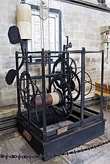 Salisbury Cathedral clock, 1386?, Salisbury Cathedral, UK
 -
 Detail of escapement


The first clocks with gear wheels controlled by a balance were intended for the use of the general public and to this end were placed in the belfries of churches and in public buildings so that passersby might know the time indicated by the dial and those who were further away could hear the clock sounding the hours
— 18th century French clockmaker Ferdinand Berthoud
In late 13th century Europe, advances in mechanical technology resulted in a breakthrough in clock design: the invention of the escapement which made the all-mechanical clock possible. The first all-mechanical clocks kept time with a verge escapement which drove either a balance wheel or a foliot, a primitive precursor to the balance wheel consisting of a horizontal bar with weights on the ends, to oscillate back and forth. This was a more accurate timekeeping technology than the water clock. The new mechanical clocks were also easier to maintain than water clocks, as the power to run the clock was provided by turning a crank to raise a weight on a cord, and they also did not freeze during winter. So the verge and foliot became the standard mechanism used in the turret clocks spreading through Europe, and remained the only clock escapement for 350 years. In the second half of the 14th century, over 500 striking turret clocks were installed in churches, cathedrals, monasteries and town halls all over Europe. The Salisbury Cathedral clock shown, built around 1386 at Salisbury Cathedral, UK, shows what these clocks looked like. It is one of the oldest working clocks in the world.
Although they were written about at the time, it is not known when the first mechanical escapement tower clock was built, because manuscript records often did not describe the clockwork mechanism. The Latin word horologe was used for both mechanical and water clocks.
The verge and foliot timekeeping mechanism in these early mechanical clocks was still very inaccurate, as the primitive foliot balance wheel did not have a balance spring to provide a restoring force, so the balance wheel was not a harmonic oscillator with an inherent resonant frequency or "beat"; its rate varied with variations in the force of the wheel train. The error in the first mechanical clocks may have been several hours per day. Therefore the clock had to be frequently reset by the passage of the sun or stars overhead.
Striking train[edit]
The earliest tower clocks, up until the 13th century, did not have faces, they were striking clocks whose only function was to ring bells. This is indicated by the origin of the word 'clock', and its cognates, which derive from the medieval Latin word for 'bell'—clogga. Often the bell in the tower was rung by a clock jack, a statue holding a mallet which turned on a pedestal, in imitation of the human workers whose job it was to ring church bells before the advent of clocks.
The earliest striking clocks simply rang the bell once on each hour; this was called a passing strike clock. Passing strike was easy to implement mechanically with a cam on the hour wheel which lifted a hammer and let it fall to hit the bell with each rotation.
The first hour strike mechanism was the countwheel, invented during the turret clock building boom in the 14th century. This consisted of a smooth wheel which rotated as the clock struck, with slots which stopped the striking when the proper number of strikes had occurred. This mechanism could easily get out of sync and start striking the wrong number of hours.
The modern mechanism used in striking clocks, called the rack and snail, was invented in the late 17th century. Although many sources erroneously attribute it to Edward Barlow, it's actual inventor is unknown.
Astronomical clocks[edit]

As tower clocks became more common in the 13th century, clockmakers realized that an indicator mounted on the outside wall of the clock tower, turned by the mechanism, would allow the community to tell the time visually between the hourly strikes.
The first clock faces were representations of the motions of the planets in the heavens, reflecting the clock's origin in astrolabes and orreries. These are now called astronomical clocks. The construction of a public clock was an expensive high-tech undertaking requiring several specialists, and was a prestige project for a town. The elaborate faces were artworks or exhibition pieces, built to impress as much as to educate or inform, to demonstrate the clockmaker's technical skill and their patrons' wealth and culture. The astronomical clock’s depiction of an ordered, heavenly-ordained clockwork universe set in motion by a Supreme Being accorded with the Gothic era European's view of the world, and helps explain their popularity.
As turret clocks proliferated and became more utilitarian, the face became a disk showing the canonical hours, which rotated once per day, with a stationary pointer, often in the shape of a human hand, indicating the current time. Later the disk was made stationary, with a rotating hand indicating the time. The clockwise motion of the hands was in imitation of the motion of a gnomon's shadow on a sundial, which in the Northern Hemisphere rotates clockwise. Until the invention of the pendulum clock, clocks had only an hour hand, as their accuracy was insufficient to justify a minute hand.
Animated public clocks[edit]

Starting in the mid-14th century elaborate clocks suddenly became a status symbol and source of civic pride for urban Europeans, and the towns of Europe competed with each other to build the most extravagant, intricate public clocks. These were not mere utilitarian timekeepers or astronomical aides, but entertainments for the community, having elaborate animated figures and depictions of the heavens set in motion every hour by intricate mechanisms geared to the clockwork which struck the bells. Lynn White Jr. writes that during this period:
- "No European community felt able to hold up its head unless in its midst the planets wheeled in cycles and epicycles, while angels trumpeted, cocks crew, and apostles, kings, and prophets marched and countermarched at the booming of the hours."
Pendulum clocks[edit]
The pendulum clock was invented and patented in 1657 by French scientist Christiaan Huygens, inspired by the superior timekeeping properties of the pendulum discovered beginning in 1602 by Italian scientist Galileo Galilei. Pendulum clocks were much more accurate than the previous foliot clocks, because the pendulum was a harmonic oscillator; it uses resonance to oscillate preferentially at a constant resonant frequency determined only by its length and resists oscillating at other rates. The pendulum improved timekeeping accuracy of the best precision clocks from 15 minutes per day to perhaps 10 seconds a day. Within a few decades most tower clocks throughout Europe were rebuilt to convert the previous verge and foliot escapement to pendulums. Almost no examples of the original verge and foliot mechanisms of these early clocks have survived to the present day.
The accuracy of the pendulum clock was increased by the invention of the anchor escapement in 1657 by Robert Hook, which quickly replaced the primitive verge escapement in pendulum clocks. The first tower clock with the new escapement was the Wadham College Clock, built at Wadham College, Oxford, UK in 1670, probably by clockmaker Joseph Knibb. The anchor escapement reduced the pendulum's width of swing from 80-100° in the verge clock to 3-6°. This greatly reduced the energy consumed by the pendulum, and allowed longer pendulums to be used. While domestic pendulum clocks usually use a seconds pendulum 1.0 meter (39 in) long, tower clocks often use a 1.5 second pendulum, 2.25 m (7.4 ft) long, or a two-second pendulum, 4 m (13 ft) long.[3][4]
Gravity escapements[edit]
Tower clocks had a source of error not found in other clocks: the varying torque on the wheel train caused by the weight of the huge external clock hands as they turned, which was made worse by seasonal snow, ice and wind loads on the hands.[5] The variations in force, applied to the pendulum by the escape wheel, caused the period of the pendulum to vary. During the 19th century specialized escapements were invented for tower clocks to mitigate this problem. In the most common type, called gravity escapements, instead of applying the force of the gear train to push the pendulum directly, the escape wheel instead lifted a weighted lever, which was then released and its weight gave the pendulum a push during its downward swing. This isolated the pendulum from variations in the drive force. One of the most widely used types was the three-legged gravity escapement invented in 1854 by Edmund Beckett (Lord Grimsthorpe).
- ^ Donald Routledge Hill (1991), "Arabic Mechanical Engineering: Survey of the Historical Sources", Arabic Sciences and Philosophy, 1 (2): 167–186 [180], doi:10.1017/S0957423900001478, S2CID 145180608
- ^ Needham 1986, p. 445.
- ^ Milham, Willis I. (1945). Time and Timekeepers. MacMillan., p.188-194
- ^ Glasgow 1885, p.282
- ^ Glasgow, David (1885). Watch and Clock Making. London: Cassel & Co. p. 308.