
User:TheodoreNg/Mixing in mineral processing
Minerals are the inorganic substances that naturally occur in the earth. Combinations of minerals in different compositions make up ores in varying sizes and shapes. Mineral processing is the processing of ores by chemical or physical methods to obtain mineral products [1]. The ores must go through a number of operations to obtain the final products. The major steps in the process are size reduction, size separation, concentration, dewatering and aqueous solution [2]. Size reduction involves crushing and grinding processes. Size separation is done by classifiers, screens or water elutriators. Concentration includes 3 main processes: froth flotation, gravity concentration, and magnetic and electrostatic concentration. Dewatering involves thickeners and filters and aqueous dissolution. The aqueous solution refers to leaching which is done in autoclave reactors. These constitute the main units that are involved in mineral processing.
In terms of the phase interactions, solid-liquid, solid-solid and liquid-liquid operations are involved. Solid-liquid operations occur mainly in flotation units, thickeners and vacuum filters [3]. Solid-solid and liquid-liquid operations take place in gravitational and magnetic separation, and extraction, respectively.
Figure 1 shows a flowsheet for a typical leaching process with a CCD (counter current decantation) and Merrill Crowe circuit [4]. There are many steps involved in this process, some of which are mentioned above. Here, and in all mineral processes, mixing is an essential unit operation, occurring in almost every step, in the thickener, leaching tanks, crystallization, mixer-settlers, in storage tanks at the end of the process, etc. The focus of this article is on solid-liquid mixing in mineral processing.
In solid liquid mixing the aim is to bring the solids and liquid into contact. There are a number of criteria that should be taken into account to design the system correctly. One of these is the solids loading. In mineral processing, the slurries have very high solids loadings and they are composed of a mixture of different minerals. This results in a complex system because the high solids loadings lead to high power consumption and having a mixture requires additional consideration in designing the equipment. Another criterion related to slurry properties is the rheology. The interactions between the solids and the liquid phase result in a range of rheological properties [5]. From a mixing point of view two rheological properties stand out for design and operation of mineral processes: the apparent viscosity and time dependence. These show up in oxygen mass transfer, and leaching kinetics. Careful design is necessary to prevent any problems during the process. Some chemical additives can be used to modify the rheological properties of the slurry [5]. The additives may change the degree of aggregation or dispersion by interacting with the particle surfaces.
The most common mixing equipment that is used in industry is stirred tank. As can be seen in Figure 1, this trend is followed in mineral processing as well. Solids suspension in stirred tanks has two key operational requirements targeting maximum mass transfer: complete off bottom suspension and even distribution of solids [6]. The complete off bottom suspension conditions requires complete motion of all particles in order to utilize the maximum surface area of the solids for mass transfer [7]. At high solids loadings, solids are suspended up to a distinct interface which is called the cloud height. Mixing times in the liquid layer above the cloud height can be 20 times longer than the solids rich volume [8]. This becomes an important issue in case of reactions. In Figure 1 stirred tanks are employed mainly for leaching. For this specific application and also for flotation the aim is not only to suspend the solids off the bottom of the tank, but also to provide sufficient gas dispersion. These are more complex systems with three phases involved.
The schematic of a typical stirred tank for solids suspension is shown in Figure 2. The tank is fully baffled. If the ratio of liquid height to tank diameter, H/T, is less than 1.3, then single impeller is sufficient for solids suspension. The number of impellers may be increased for taller tanks [7]. Axial impellers, such as Lightnin A310, A320, A340, Chemineer HE3 are efficient for solids suspension; however, a different impeller or a dual impeller system may be required for gas-liquid-solid systems such as leaching operations. The size of an industrial stirred tank may be very large compared to a lab scale tank; therefore, scale up is important in these systems. Figure 3 shows the size of an industrial scale impeller in a stirred tank for mineral processing. This gives an idea of the large scales used in industry. If a PBT is used D/T < 0.25 is sufficient to provide solids suspension, where D/T is the ratio of impeller diameter to tank diameter.
Mineral processing is one of the largest areas of application for solid-liquid mixing. The aim is the efficient interaction of the liquid and the solids. The rest of this article focuses on the solids suspension phenomenon, and the froth flotation, leaching and mixer-settler operations.
Solid-Liquid Mixing[edit]
The purpose of solid-liquid mixing is to improve the mass transfer between solid and liquid phases. This objective is accomplished by making the surface area of all the solids available for mass transfer. In a typical mineral extraction process where minerals in ore leach into a fluid medium, such as in uranium processing, mineral value is extracted from high solid concentration slurries. This process requires a high amount of uniformity to increase the leaching rate of the desirable mineral.
Solid Suspension[edit]
Solid suspension is accomplished by the addition of mechanical energy into the system through some form of agitation. The agitation acts on the solid particles by a combination of lift and drag forces created by turbulent bursts as seen in Figure 4. The hydrodynamics of the system are affected by the properties of the liquid, the solid particles, vessel geometry, and agitation method [7].
In an agitated solid suspension the particle settling velocity is a function of, and is always less than, the free settling velocity [11].
States of Solid Suspension[edit]
As shown in Figure 5 the three levels of solid suspension are: On-bottom motion, off-bottom and uniform suspension. On-bottom motion is characterized by the complete motion of all the particles at the bottom of the vessel. In this state not all the particles are suspended. At off-bottom suspension all particles are in complete motion and no particles remain on the base of the vessel for more than 1 to 2 seconds. This is known as the Zwietering criterion [12] and the impeller speed that satisfies this criterion is called the just suspended speed, Njs. In a uniform suspension the solid particles are evenly distributed throughout the vessel and any increase in agitation does not significantly improve solid distribution [7].
The power consumption (P) is an important concern in design of these systems.

ρsl: density of the slurry (kg/m^3)
Np: power number
N: impeller speed (rps)
D: impeller diameter (m)
Power consumption increases significantly with increasing N and D. If the process objective is mass transfer, it is better to operate at Njs to utilize all surface area of solids at the minimum impeller speed. Njs can be determined by correlations or by experiments. The following correlation was suggested by Zwietering (1958) [12].

- - Zwietering Njs constant which is a function of impeller and tank geometry. The S values for various configurations can be found in the literature [12, 13].

- - kinematic viscosity, m^2/s

- - gravitational acceleration, 9.81 m/s^2

- - density, of solid and liquid, kg/m^3

- -solids loadings ((kg solids/kg liquid) x 100)

- - mean diameter of solid particles, m

- - impeller diameter, m

Cloud Height[edit]
In stirred tanks with greater than 10 weight percent solid loading, a clear interface may form between the solids rich volume in the lower portion of the tank and the clear liquid volume close to liquid surface. The height of this interface is called the cloud height [7]. Solid particles only rarely penetrate into the clear liquid volume. This phenomenon is important to mineral processing because blend time can up to twenty times longer in the solid-free phase than the solid rich volume [8]. This is important in slurry catalyst reactor design because of the limited mixing between the two layers [6].
Jet Mixers[edit]
Jet mixers are not frequently used in industry for solids suspension; however, occasionally may be used as an alternative for an expensive retrofit. For example, if a process containing a liquid storage vessel experiences a process upset, then sludge or solids may accumulate. In this case it might be more difficult or expensive to install a mechanical agitator instead of using a jet mixer [7]. The minimum jet velocity to reach the off-bottom suspension is known as the just suspended jet velocity, Vjs [7].

- : tank diameter (m)

- : jet diameter (m)

- : percentage weight fraction of solids.

Mass Transfer[edit]
In mineral processing mass transfer is important in the final product quality; therefore, better mass transfer is desired. Solid-liquid mixing only has an effect on film diffusion. The rate of diffusional mass transfer can be calculated with [7]
![{\displaystyle M=k_{sl}a_{p}([A^{*}]-[A])}](https://wikimedia.org/api/rest_v1/media/math/render/svg/2cf8d273467617d8f5e2d917b408493b8bd3eff3)
- : diffusional mass transfer coefficient (m/s)

- : concentration driving force (mol/m^3)
![{\displaystyle ([A^{*}]-[A])}](https://wikimedia.org/api/rest_v1/media/math/render/svg/8da03b07a58e13b2373f7514b25529650c02994a)
- : interfacial area for mass transfer per volume of fluid (m^2/m^3)


- : solid loading (g/cm^3 solid-free liquid)

Mechanical agitation mainly affects the thickness of the diffusional boundary layer surrounding the solid [7]. The relative mass transfer increases steeply until complete suspension is achieved. After this, the mass transfer rate increases more slowly.
The following equation is useful for estimating [14]

Sh: Sherwood number

- : particle Reynolds number


Sc: [Schmidt number]

Where,
- : diffusivity

- : terminal velocity of the particles

- : viscosity of the liquid.

For systems with a << 0.0005m/s the correlation becomes [15, 16]

In this equation, is defined in terms of which is the power per unit mass:


Froth Flotation[edit]
Froth flotation is used in the mineral processing industry to separate hydrophobic value minerals from hydrophilic gangue. The hydrophobicity of a particle is determined by the contact angle it forms when collision occurs with a rising bubble [17]. Figure 6 shows the contact angle for a gas-liquid-solid system.
The contact angle may be altered by the addition of reagents prior to the flotation process. There are many factors that determine the success of floating a hydrophobic particle within a flotation cell: bubble diameter, turbulence within the cell, velocity of rising air bubbles, contact angle, collision efficiency, attachment efficiency, and stability efficiency. Several of these key parameters are influenced by the mixing that occurs within the flotation cell.
The schematic of a flotation cell is shown in Figure 7. Mechanically agitated flotation cells utilize an impeller to provide the agitation necessary for breaking air into bubbles and dispersing them throughout the cell while suspending solids long enough for bubble-particle agglomerates to form. It also creates the micro-turbulence necessary to facilitate bubble-particle collision. Air enters the cell through a concentric pipe surrounding the impeller shaft. The rotating impeller tips create a high-shear zone where air is broken up into a dispersion of bubbles. The bubble formation is shown in Figure 8. The bubbles are flung outwards from the impeller tips and scattered throughout the solid-liquid mixture (slurry) within the cell.
The power dissipation per unit mass (mean energy dissipation, ε) influences the size of the bubbles [7]. ε can be calculated with [7, 19]

P: power (W)
- : density of the slurry (kg/m^3)

V: volume of the slurry (kg/m^3)
N: impeller rotational speed (rps)
D: impeller diameter (m)
k: geometric constant for a given impeller. Derived from the impeller swept volume.
The energy dissipation at the tip of the impeller is ~20 times greater than the average for the entire flotation cell [7, 19].
The frequency of bubble-particle collisions, Z, determines the flotation rate for a system. An increase in dissipation rate leads to a greater frequency of collisions and therefore a higher flotation rate [19].
Impeller Rotational Speed[edit]
The effect of impeller speed is highly dependent on particle size; therefore, it is advantageous to separate fine and coarse material prior to the flotation step.
For fine particles a high impeller rotational speed causes greater energy dissipation. The collision frequency increases and this increase in collisions results in a higher flotation rate.
The opposite is observed overall for coarse particles. Higher rotational speeds increase the impeller tip speed and turbulence within the cell. An increase in tip speed causes bubble velocity to rise which in turn lowers the contact time between bubbles and particles. An increase in turbulence causes coarse particle-laden bubbles to readily burst and particle detachment to occur. These two factors contribute to a reduced flotation rate for coarse particles. In Figure 9 the bubble size is given as a function of Jg.
The bubble size within the collection zone is not affected by impeller rotational speed [19].
Power Input[edit]
Power input may be used to increase flotation rate up to a certain point. As power input to the impeller is increased, the attachment rate increases until a certain maximum flotation rate is reached. At this point, any further increase in power input results in a large decrease in attachment rate and consequently an increase in overall detachment rate [19].
Impeller Selection[edit]
Most impellers are up-pumping and consist of a flat, circular disc with blades fitted concentrically to the disk’s lower section. The shape of the blade varies from cylindrical to half-spherical depending on the process. The submergence of the impeller depends on cell type/geometry and method of air introduction to the cell [18]. Typical flow patterns, impellers and rotators for a flotation cell are given in Figures 10 and 11, respectively.
Leaching[edit]
Leaching is a solvent extraction process that is used to extract metal from solubsalt in aqua media by using organic solvents [20]. There are three phases present in a leaching process: gas, liquid and solid. The reaction takes place at the interface between the phases; hence, diffusion has initiation role in the start-up of the process and also in final step of the separation process which is the diffusion of the products. Mixing has an important role in increasing the diffusion by enhancing the contact between the phases [20, 21].
Diffusion, adsorption, reaction, desorption and product diffusion are the different steps of the leaching process. Reactants diffuse through the diffusion layer and are adsorbed onto solid surfaces where they react. This step is slower than diffusion and the surface area is reduced with time; therefore, this step is the rate-limiting step which controls the leaching operation. The next step is desorption where the products are desorbed from the solid after reaction and diffuse through diffusion layer into the leaching solution. At the end of the process the viscosity may be significantly different than the beginning; therefore, this should be taken under consideration while designing these systems [21, 7].Figure 12 shows the change in concentration of the reactant along the diffusion layer.
Types of leaching:[edit]
- Dump leaching: The leach material is placed in a large container sump which has a porbottom. Then the leaching solution is sprayed on to the leaching heap. As soon as the solution has penetrated the heap, it is collected in a channel from which it is circulated back after the extraction of the metal [22].
- Tank leaching: This method is applicable for fine-grained leach material in high grade bodies. Leaching material is suspended and kept in motion by mechanical stirring, compressed air or pumping. By producing turbulence, leaching time that is significantly shorter than dump leaching can be obtained. This process is mostly continuous [22].
- Heap leaching: Ores are spread on particular pad arrangement and the leaching solution is sprayed onto the leaching heap through sprinklers and allowed to saturate it. Eventually the leaching solution is extracted and returned back to reuse. This process is slow and only applicable for very low grade ores [22].
- In-situ leaching: This is suitable for low grade copper and uranium ores. In this process the solution contacts the ore on the spot to fragment the ore. This is slow and the efficiency is low [22].
Autoclave leaching reactors and mixing roles[edit]
Leaching autoclaves are vessels. They are built in different configurations such as horizontal, vertical or long horizontal tubes. They mostly contain four to six compartments to create similar conditions to a series of CSTR’S. This is done by transferring and passing the leaching solution from one chamber to the next, dispersing oxygen or air to improve solids suspension and distributing the solvent. This helps in preventing dead zones. Sometimes steam and air are used to control the shear. Steam can be used for heat transfer purposes as well [23. 24, 25]. Figures 13 and 14 are shown examples of autoclave reactors.
The maximum extraction efficiency in an autoclave reactor must be obtained within the minimum number of stages. The inter-stage wall between different compartments in an autoclave has a considerable effect on residence time distribution. The solvent and slurry streams are conducted into the front head by using a mixer in such a way that short circuiting does not occur. In scale-up from pilot to full scale, the residence time distribution is more important than residence time just by itself in individual steps. Residence time distribution is affected by the design of baffles, the height and the number of inter stage walls and slurry and solvent inlet pipe specifications [23, 24, 25].
Leaching autoclave reactors are equipped with an agitator to completely combine reagents, suspend fine solids and disperse phases as well as adjust the leaching rates between phases to improve the leaching process. In horizontal autoclaves the impellers are located close to the bottom of the tank in order to suspend the solids efficiently. Depending on the application and process limitations of kinetics or mass transfer, different impellers are designed to focus on blending, solids suspension or heat and mass transfer [23, 24].
The leaching process can be improved by modifying the mixing equipment. For example a dual impeller system with a Rushton turbine close to the bottom combined with a pitched blade turbine close to the surface operate very efficiently for gas dispersion and primary solid suspensions. In addition to that, Lightnin A340 impellers show very good performance [20].
Mixers-Settlers[edit]
Extraction processes are widely used in the hydrometallurgical industry. Mixing increases the mass transfer rate between phases and increasing mass transfer rate promotes extraction efficiency. Increasing the agitation rate also causes a decrease in drop size and the velocity between the continuous and dispersed phases which in return reduces throughput. Stage efficiency also decreases with increasing axial mixing. This is more significant at high agitation speeds; therefore, axial mixing must be reduced or eliminated to improve phase separation. The solution is to use a mixer-settler which transfers solute from one phase to another.
The purpose of using a mixer settler is to extract the target metal from the solution. A mixer-settler has two main parts, a mixer to mix the phases and a settler to separate the phases. Figure 15 shows a mixer-settler unit. If a mixer and settler are used side by side, rather than just using a settler better results are obtained. Using mixer-settlers in series may also give good results depending on process specifications [28, 29, 30, 31].
Types of mixer-settlers[edit]
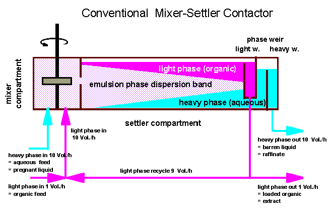
- Conventional mixer-settler: The inlet stream consists of different layers of effluents requiring separation. An agitated tank may be a mixer or mix box, depending on the retention time required. Large pump-mixer type agitators are used in a mixed box which works at low speed and low shear for pumping and mixing simultaneously. Variable speed drives and a special design make this device very successful at preventing fine droplet formation and air entrainment which retain coalescence in the settlers. A recycle stream is always used from a settler to a mix box in order to keep the phase ratio constant [30]. Figures 16 and 17 are shown conventional mixer-settlers.
- Krebs: This is smaller in size, lower in capacity and easier to maintain than the conventional type, but it is more difficult to monitor the operating conditions. The numbers of mix boxes per stage depends on the solution flow rates and the required retention time. If two mix boxes are used, the first is equipped with a pump-mix type agitator. The primary separation of the organic and aqueous phases is almost complete at the discharge of the upper launder. This enables the phases to be directed separately to the main settler below, entering via a baffle system [30].
- Reverse flow mixer settler: Applicable in large copper, nickel, cobalt and zinc production plant, but not as efficient as conventional mixer-settler for same size application. It is used as an alternative to conventional mixer-settlers. The main difference from the conventional mixer-settler is the use of a side mounted launder to direct the dispersion from the mix boxes to the opposite end of the settler. The mix boxes and settler are essentially same a conventional units [30].
- Vertical smooth flow (VSF) mixer-settler: This is for a large scale solvent extraction copper plant. In this process mixing and pumping are divided functionally between a couple of helix mixers and an impeller to agitate at low shear conditions. Low operating cost, uniform drop size, and high efficiency can be obtained, but still the conventional mixer-settlers are smaller in size and capital requirement [30]. Figure 18 shows a VSF mixer-settler.
- Combined mixer settler (McKee-CMS): This is for uranium processes. The mixing and phase separation take place in one vessel. It works in different organic and aqueous ratios at various heights. It is suitable for smaller scale production and lower capital cost requirement; however, due high organic effluent organic recovery units are required which increases the costs [30].
- Lurgi mixer-settler: This is commonly used for commercial uranium plants. It employs multiple trays for separation. These units are less than half the size of conventional units. Capital investment may be lower than the conventional mixer-settlers depending on the ore [30].
- IMI mixer-settler: This is used in uranium plants. The axial flow disperses the contents of collecting launder and sends it to cylindrical settler via a distributer system. IMI mixers have higher separation efficiency, lower capital cost and reduced capacity in compared to conventional mixer-settlers; however, the operating cost is higher [30].
- In line mixer-settler: This is applicable for uranium plants as well. This unit has a baffled cylindrical vessel equipped with a Kenics mixer which is mounted in the dispersion zone downstream of the entrance. A turbulence regime exists here and back mixing dominated. Low capital and operating cost are the advantages, but limited accesses to inner parts are process disadvantages [30].
References[edit]
As of 30 July 2010, this article uses content from "Mixing in Mineral Processing" by Inci Ayranci, Glendon Tan, Mikaela Dix-Cooper, and Mahmoud Hossein-pour, which is licensed in a way that permits reuse under the Creative Commons Attribution-ShareAlike 3.0 Unported License, but not under the GFDL. All relevant terms must be followed.
1. Nagaraj, D.R., 2005, Minerals recovery and processing, Kirk-Othmer Encyclopaedia of Chemical Technology.
2. Fuerstenau M.C. and K.N. Han, 2003, Principles of mineral processing, SME.
3. Silverblatt. C.E., 2002, Characterization of process objectives and general approach to equipment selection, Mineral Processing Plant Design, Practice, and Control Proceedings, 2, 1255-1261.
4. Hampton, P.A., 2002, Zinc Cementation – The Merrill Crowe Process, Mineral Processing Plant Design, Practice, and Control Proceedings, 2, 1663-1679.
5. Klein, B. M. Pawlik, 2005, Rheology modifiers for mineral suspensions, Minerals and Metallurgical Processing, 22 (2), 83-88.
6. Bittorf, K.J. and S.M. Kresta, 2003, Prediction of cloud height for solid suspension in stirred tanks, Trans IChemE, 81(A), 568-577.
7. Paul E.L., V.A. Atiemo-Obeng and S.M. Kresta, 2004, Handbook of Industrial Mixing, Science and Practice, John Wiley & Sons, Inc., Hoboken, New Jersey.
8. Bujalski, W., K. Takenaka, S. Polini, M. Jahoda, A. Paglianti, K. Takahashi, A.W. Nienow, A.W. Etchells, 1999, Suspension and liquid homogenization in high solids concentration stirred chemical reactors, Trans IChemE, 77(A), 241-247.
9. http://www.philamixers.com/admin/userfiles/file/pdf/Mining%20Applications.pdf
10. Cleaver, J. W., and B. Yates, 1973, Mechanism of detachment of colloidal particles from a flat substrate in turbulent flow, J. Colloid Interface Sci., 44, 464.
11. Guiraud, P., J. Costes, and J. Bertrand, 1997, Local measurements of fluid and particle velocities in a stirred suspension, Chem.Eng. J., 68, 75-86.
12. Zwietering, T. N., 1958, Suspending of solid particles in liquid by agitators, Chem. Eng. Sci., 8, 244.
13. Ibrahim, S. and A.W. Nienow, 1996, Particle suspension in the turbulent regime: The effect of impeller type and impeller/vessel configuration, Trans IChemE, 74, Part A, 679-688.
14. Nienow, A. W., and D. Miles, 1978, The effect of impeller/tank configurations on fluid–particle mass transfer, Chem. Eng. J., 15, 13.
15. Levins, D. M., and J. Glastonbury, 1972a, Application of Kolmogoroff’s theory to particle–liquid mass transfer in agitated vessels, Chem. Eng. Sci., 27, 537–542.
16. Levins, D. M., and J. Glastonbury, 1972a, Particle–liquid hydrodynamics and mass transfer in a stirred vessel, Trans. Inst. Chem Eng., 50, 132–146.
17. Perry, R.H. and D.W. Green, 1997, Perry's Chemical Engineers' Handbook, 7th Edition, McGraw-Hill, NY.
18. Gorain, B.K., J.P. Franzidis, and E.V. Maniapig, 2007, Flotation Cell Design: Application of Fundamental Principles, Encyclopedia of Separation Science, 1502-1512.
19. Grano, S., 2006, Effect of impeller rotational speed on the size dependent flotation rate of galena in full scale plant cells, Minerals Engineering, 19, 1307-1318.
20. Gigas, B. and J. Wilmot, 2006, Computational Analysis of Improved Pressure Leach Vessel Agitator Design, ALTA Conference program. Available from: http://www.altamet.com.au/documents.
21. Åke Sandström, A., Hydrometallurgy. Chapter 4: Leaching theory, The FP6 BioMInE project, funded by the European Union. Retrieved March 7, 2010 from: http://biomine.skelleftea.se/html/BioMine/Hydrometallurgy/Hydrmetallurgy%204.pdf
22. Åke Sandström, A., Hydrometallurgy: Chapter 6: Leaching Methods, The FP6 BioMInE project, funded by the European Union. Retrieved Feb 25, 2010. Available from: http://biomine.skelleftea.se/html/BioMine/Hydrometallurgy/Hydrmetallurgy%204.pdf
23. Gigas, B. and M. Greaves, 2007, Laterite Nickel HPAL Agitation Design, Proceedings of ALTA 2007 Nickel/Cobalt Conference, ALTA Metallurgical Services, Perth, Australia.
24. Gigas, B. and M. Greaves, 2008, Autoclave Design Beyond Agitators – Slurry and Acid Lances, ALTA 2008 Nickel-Cobalt Sessions
25. Adams, D., M. Preston, T. Post, 1998, Mixing Optimization of High Pressure Oxidation of Gold Ore Slurries, Randol Gold Proceedings.
26. Banker, J.G., Titanium Clad Autoclave Performance in Nickel Laterite Hydrometallurgy Retrieved Feb 28, 2010 from www.dynamicmaterials.com
27. Trexler, D.T., T. Flynn, J.L. Hendrix, 1990, Heap Leaching, GHC Bulletin.
28. Treybal, R.E., 1987, Mass Transfer Operations, 3rd Edition, McGrawHill, New York, Chapter 10, 109-111.
29. Rahn, R.W. and M. Smutz, 1969, Development of a Laboratory Scale Continuous Multistage Extractor, Ind. Eng. Chem. Process Des. Dev., 8 (3), 289–293.
30. Taylor, A., Review of Mixer-Settler Types And Other Possible Contactors For Copper Sx., ALTA Metallurgical Services. Retrieved Feb 25, 2010 from: http://www.altamet.com.au/Technical%20Papers%20and%20Articles/
31. Taylor, A. and M.L. Jansen, Solvent Extraction Mixer-Settler Design. Retrieved March 1, 2010 from: http://www.altamet.com.au/Technical%20Papers%20and%20Articles/Others/SX%20Mixer-Settler%20Design.pdf
32. Rousselet Robatel Laboratory Mixer-Settlers, Operating Principle. Retrieved Feb 27, 2010 from: http://rousselet-robatel.com/products/pdfs/mixer-settler-operating-principle.pdf
33. Hydrometallurgical technologies. Retrieved March 2, 2010 from www.outotec.com/38049.epibrw
34. General Layout of a Mixer-Settler for Copper Solvent Extraction. Retrieved March 8, 2010 from: http://www.postmixing.com/mixing%20forum/Macro/Liq-Liq/Mixer-Settlers/mixer-settlers.htm
35. Conventional Mixer-Settler Contactor. Retrieved March 8, 2010 from: http://www.halwachs.de/mixersettler.gif