
User:WillWare/BluetoothBitBang


The Bluetooth Bit Bang is a gadget I am developing to assist electronic engineers and hobbyists in debugging or studying circuits. It is an Android app and a piece of hardware, which allow you to monitor or drive digital signals. Think of it as a quick and dirty logic analyzer with signal-driving capability. The commands for writing and reading digital lines are very simple, so people who want to write an iPhone app to replace the Android app (or want to run the hardware from a laptop with a Bluetooth dongle) can do that pretty easily.
With the approaching tsunami of tablets promised at CES, we can start to build self-contained hand-held instruments that encroach on the territory now held by USB oscilloscopes, logic analyzers, signal generators, etcetera, where the tablet provides a user interface, and connects to data acquisition hardware by USB or Bluetooth. This project is a very small first step in that direction. In addition to electronic test instruments, this might be a convenient way to set up lab automation equipment and non-critical medical instruments, and there may be applications in home and building security.
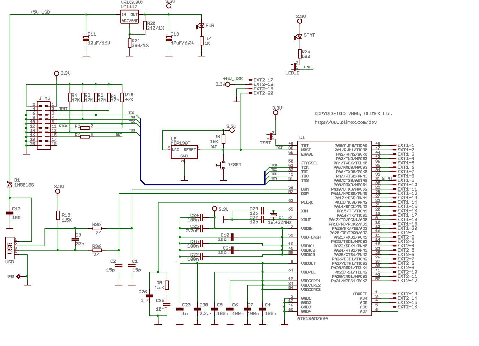
The pieces involved are a AT91SAM7S microcontroller board (schematic), a BTM-182 Bluetooth serial port module, and an Android phone (mine is an HTC Droid Incredible). The BTM-182 provides 115.2kbaud serial communication between an application running on the phone and a little command interpreter running on the SAM7 board. This is used to manually write and read some GPIO bits from a graphical user interface on the phone. Unlike a USB instrument, this gadget has no external power source, so it has some AA batteries driving the SAM7 board's 3.3-volt regulator to power both the SAM7 and the BTM-182. I'm working with Sparkfun's $35 BTM-182 breakout board, but with a little fine soldering you can use the bare module for $15. The SAM7 board costs $36.
The firmware running on the SAM7 watches for command bytes coming from the phone over the bidirectional serial port and assembling them into commands, running the command when complete. It also watches the inputs for changes and sends an unsolicited notification whenever a change is detected.
I've blogged about this thing.
The Android app is available in the Android Market (now called Google Play - really?? who thinks of these things?)
Code[edit]
The AT91SAM7S firmware and the Android app are both on Github.
Future stuff[edit]
- Use UART interrupts on the SAM7, and clean up SAM7 code in general.
- Post a user manual and a tech reference (in HTML and PDF) describing both the Android app and the SAM7 stuff.
It would be good to design a bus allowing multiple instruments to share a single Bluetooth connection. SPI looks good but I need to figure out how to accept unsolicited notifications from instruments on the bus. Think about discoverability, so that new devices can be wired to the bus without changing the SAM7 firmware.
- Discovering that an instrument is present at a particular SPI address.
- Determining what information the instrument provides, what byte order, what physical units, any relevant time constants or other contextual information.
The bus should be simple, and well-documented so that people can easily interface their instruments to it. USB HID reports are a nice example of a WSDL-like discoverable protocol for hardware.