
Talk:RLC circuit/Archive 2
| This is an archive of past discussions about RLC circuit. Do not edit the contents of this page. If you wish to start a new discussion or revive an old one, please do so on the current talk page. |
| Archive 1 | Archive 2 |
"A pure LC circuit is an ideal which really only exists in theory"
"A pure LC circuit is an ideal which really only exists in theory" -> What about using superconductors? — Preceding unsigned comment added by 81.155.137.204 (talk) 08:31, 19 June 2013 (UTC)
Just give us the formula already?!
I found this article from Google because I wanted the formula for resonant frequency of an RLC circuit. I don't want the angular frequency or anything like that, I just want the formula so I can calculate the resonant frequency. Why is this not here?! I found it from some silly "answers" website... 86.30.129.146 (talk) 00:41, 3 April 2013 (UTC)
- Just divide by 2π. SpinningSpark 06:51, 3 April 2013 (UTC)
It is blindingly obvious that they had it: (The first one is in the introduction because frankly that should be known to you if you've studied this or anything involving angular motion)
- — Preceding unsigned comment added by 81.155.137.204 (talk) 08:36, 19 June 2013 (UTC)


Mistake in the RLC circuit derivation
In the series RLC circuit there might be a mistake in the following step of the derivation:

For the case where the source is an unchanging voltage, differentiating and dividing by L leads to the second order differential equation with :

>> There is no differentiating involved from the first step to the second - only the current is replaced by the charge and it is assumed that the oscillator is not driven by an external force.
- The expressions were changed in this series of edits by an IP editor without explanation. I have reverted them for now, at least until the edit can be explained and implemented without inconsistency. SpinningSpark 12:32, 7 July 2013 (UTC)
Parallel RLC Circuit Schematic
I think the image showing the Parallel RLC schematic is incorrect. It does not make sense to connect a voltage source to a shunt resistor, because that simply passes additional current through the resistor without affecting LC tank circuit. So the correct diagram should either replace the voltage source with a current source (with the resistor remaining shunt), or it should turn the resistor so that it is in series with the voltage source. Either would be a correct form of the parallel circuit. First Harmonic (talk) 23:55, 16 August 2008 (UTC)
- Agreed. This was just pointed out to me. The version with the current source is the dual of the series version with the voltage source, so here is an alternate version:

- In my defense, lots of other people do it that way:
- http://commons.wikimedia.org/wiki/File:Parallel_circuit%28RLC%29.gif
- http://commons.wikimedia.org/wiki/File:Graphe_liaison_circuit_RLC.svg
- http://commons.wikimedia.org/wiki/File:Rafras.png
- http://www.ycars.org/EFRA/Module%20A/AC%20Circuit%20Analysis%205.htm
- http://www.play-hookey.com/ac_theory/ac_rlc_parallel.html
- http://www.electronics-tutorials.ws/accircuits/parallel-circuit.html
- http://www.electronics-tutorials.ws/accircuits/parallel-resonance.html
- http://people.sinclair.edu/nickreeder/eet155/mod07.htm
- http://www.tpub.com/neets/book2/4l.htm
- http://www.wolframalpha.com/entities/calculators/parallel_RLC_circuit/ze/2g/se/
- http://www.rficdesign.com/parallel-rlc-circuit?wpmp_switcher=desktop
- In case the voltage source version still has some legitimate use, I uploaded under a different filename, which can be replaced on a per-article basis. http://commons.wikimedia.org/wiki/File:RLC_parallel_circuit.png#globalusage I think my images are pretty ugly, incidentally, and anyone who wants to make a nice SVG version is welcome. — Omegatron (talk) 23:29, 25 April 2011 (UTC)


- The voltage source version makes perfect sense in terms of this article which plots current against frequency. That is, the current is taken as the output, not the voltage. Doing it the other way round would require the plot to be modified (which would then become identical to the shape of the series case since, as you point out, this is the dual circuit, and would make the article less informative in my opinion) and probably some of the text and formulae also. Admittedly, if this circuit were the collector load of a transistor (common application) then the source would be more like a current source than a voltage source but this article just covers basics, not specific circuit applications.
- As for the drawing quality, I left them alone when I revamped the article because they were servicable and I did not want to be seen to be imposing my own style on other editors. But if you like, I can produce replacements in the same style as my other contributions to this article such as the one here (style, not content). SpinningSpark 06:40, 26 April 2011 (UTC)
- If you solve the parallel RLC circuit with a voltage input and current output (as shown in the existing Fig. 5), you will get a transfer function H(s)=Iout/Vin which is nonsensical (the numerator polynomial is higher order than the denominator). If you solve parallel RLC with the (correct) current input and voltage output, you will get a standard second-order transfer function with damping etc. which matches the equations in the text for alpha, damping, and Q.
- Correcting Fig. 5 does not change the admittance analysis in the "Frequency domain" section. For the admittance analysis, the input source is not part of the calculation. Nevertheless, the description of Fig. 6 is confusing because it describes driving the circuit with a "constant voltage", when you really mean "sinusoidal voltage of constant amplitude".
- I recommend replacing Fig. 5 with Omegatron's revised diagram.Stevens94 (talk) 16:07, 4 May 2011 (UTC)
- I'm not really following your objection here. It is hard to see how a solution that has a physical reality (voltage input and current output) can be characterised as "nonsensical". SpinningSpark 19:37, 4 May 2011 (UTC)
- sorry for not being clearer. What I am saying that the idea of the circuit having an alpha, zeta, or Q does not apply when the input is a voltage. You are correct that you do get meaningful physical results if you look at it from an equivalent impedance (or admittance) standpoint.Stevens94 (talk) 21:22, 4 May 2011 (UTC)
I think it makes more sense to use the dual version with the current source. As pointed out, the resistor in parallel with the voltage source doesn't really do anything, so it might as well be LC circuit
Don't be afraid to replace images. I don't own the article. I like the style of images created with File:Electrical_symbols_library.svg myself, which would use components like this:
— Omegatron (talk) 03:26, 6 May 2011 (UTC)
It all depends on how you define resonance. The easiest, most consistent, fundamental and clear definition of resonance is maximum power dissipation. I am frankly suprised that power dissipation and half power points do not feature more in this entry. In any case, there are a number of definitions of resonance which are not even mentioned in this entry making it incomplete. If you accept (you may not)that power resonance is relevant, then it is necessary to use a voltage source for a series resonant circuit and a current source for a parallel circuit.Monicandave (talk) 22:25, 7 January 2012 (UTC)
There is something seriously wacky with this article. Firstly the series tuned circuit should be driven by a series current source, while the parallel tuned circuit should be driven by a parallel voltage source. More importantly the loss resistance should be a low value series resistor in the series case and a high value parallel resistor in the parallel case, and the standard formula should be given to convert between the two (multiply by Q squared). The point is that there is essentially NO DIFFERENCE between a Parallel and a Series tuned circuit (the exception is with low values of Q for a series circuit, but not if the resistor is split to maintain symmetry). Claiming there is a difference between a Parallel and a Series tuned circuit shows a series misunderstanding of the basics. 183.89.113.215 (talk) 10:07, 5 August 2013 (UTC)
Re: "Parallel RLC circuit". The following statement is confusing: "This means that a wide band, low Q circuit in one topology will become a narrow band, high Q circuit in the other topology when constructed from components with identical values". Surely you would not convert from a Series to a Parallel tuned circuit without using the equivalent parallel value resistor (e.g. multiply by Q squared). 183.89.113.215 (talk) 10:49, 5 August 2013 (UTC)
Bizarre circuit image
Surely somebody has a photograph of a real RLC circuit, and not the bizarre Photoshopped image that's currently being used? I can't imagine why someone felt compelled make such a strange image that is clearly pieces of other photographs cut and pasted together. It looks like something made with MS Paint. — Preceding unsigned comment added by 130.65.158.75 (talk) 18:54, 4 April 2013 (UTC)
- Yes, that photo is ludicrous. If no one (with a WP account) deletes that photo soon, I'm gonna do it.
- Now a breadboarded or soldered RLC circuit connected to an AC signal generator, that would be a good figure. But us humble IPs cannot upload such an image. 12.226.82.60 (talk) 04:30, 29 September 2013 (UTC)
Photo at top
Photo at top shows OPEN circuit. 71.139.161.36 (talk) 04:24, 17 April 2015 (UTC)
Questions and comments about some images
1. What is the purpose of circuits like the ones in figures 7 and 8? Would they be used in low-pass, high-pass, notch, bandpass or some other filters?
2. I don't think figures 12 and 13 are correct. I think figure 12 should have the resistor in series with the tank and I think figure 13 should have the resistor in series with the inductor and the capacitor. I simulated a variety of combination of LRC circuits in PSpice and I don't see how the output can be where they are shown. The input matches the output and the Bode plots I get are obviously flat.
ICE77 (talk) 08:40, 17 June 2015 (UTC)
- Figure 7, as explained in the text, is the equivalent circuit of a practical parallel resonator taking into account the inductor winding resistance. Figure 8, also explained in the text, is the equivalent circuit of a series resonator taking account of the capacitor dielectric loss. Resistors are not commonly deliberately inserted into filter circuits as an actual component, although Zobel networks sometimes do something similar to cvompensate for lossy components and maintain the correct input impedance.
- Figure 12 is pretty much the equivalent circuit of the output of a tuned amplifier. There must, of course, be some impedance in the source for the circuit to work into – ideally a constant current source. Similarly for figure 13, which is a configuration used for wave traps, see this book for instance. I daresay you have assumed an ideal voltage source in PSpice, so it is not surprising you get flat responses.
- SpinningSpark 19:43, 17 June 2015 (UTC)
Questions and comments about an equation
@Spinningspark: I would like to ask why the lower limit of integration of the second equation in the section "series RLC circuit" RI(t) + LdI(t)⁄dt+∫t-∞I(τ)d(τ)= V(t) is -∞. www.rapidtables.com states that "the capacitor's momentary voltage Vc(t) is equal to the initial voltage of the capacitor, plus 1/C times the integral of the capacitor's momentary current Ic(t) over time t." (see the formula in the link in the section "Capacitor's voltage") Is this conclusion correct? If so, then can I replace the integral term in this equation ∫t-∞I(τ)d(τ) with V(0)+∫t0I(τ)d(τ) since the improper integral may be undefined? Onmaditque (talk) 12:14, 1 July 2017 (UTC)
- Yes, the integral from −∞ to 0 will be the initial capacitor voltage at t=0 if we assume that the capacitor had no charge when it was created. SpinningSpark 14:23, 1 July 2017 (UTC)
Where does the term "fractional bandwidth" and symbol come from?

I don't think it's a problem using the words "fractional bandwidth" and to express that as , but giving it a mathematical symbol like seems like an ugly neologism. Shouldn't this (in addition to the photoshopped RLC circuit "photo") be removed? 173.48.62.104 (talk) 01:59, 12 November 2015 (UTC)

- I don't think it is very important what symbol we use as long as the article is self-consistent, but I have now changed it to per this book. Using B or BW for bandwidth is widespread and this book uses the similar for fractional bandwidth. There is no widely used symbol for fractional bandwidth; this book uses to distinguish it from absolute bandwidth and this book uses . Many authors do not define a symbol at all. SpinningSpark 09:29, 6 July 2017 (UTC)


Tuned response function.
I have interest in the equation that gives the amplitude of the current (or the voltage across the resistor) in a voltage exicted series RLC circuit but using only the parameters: Q and omega0,(Where Q is the quality factor of the complete circuit and omega0 is the undamped resonant radian frequency of the circuit). I need the equation to be a function of omega (the driving frequency),omega0 and Q only please. I have searched all over the web and all the books i can find. Yet I cannot find the formula for the amplitude against radian frequency. This is not homework but a personal interest. Its too hard for any homework and doesnt seem to be covered anywhere. Help!!!213.205.242.154 (talk) 23:45, 19 December 2018 (UTC)
Can someone ask that sparky spinner to look at this, He.she seems to be very clever.213.205.242.154 (talk) 23:47, 19 December 2018 (UTC)
Suggested image upgrade
I didn't read this article carefully, but I needed one where it was explicitly clear that it was an alternating current. You may wish to make the substitution shown below:
-

-
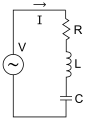 improved: c:File:RLC series circuit v2.svg


- I plan to use it on simple:Phasor --Guy vandegrift (talk) 02:27, 6 November 2018 (UTC)
- Note that the circuit is not exclusive to steady AC applications. Applications involving transients also exist. SpinningSpark 16:24, 6 November 2018 (UTC)
- I agree that the suggestion of a change to an alternating current source would be beneficial and avoid confusion in the readers.--213.205.242.154 (talk) 02:46, 20 December 2018 (UTC)
- Note that the circuit is not exclusive to steady AC applications. Applications involving transients also exist. SpinningSpark 16:24, 6 November 2018 (UTC)