
User:Marcoflagg
A Long Baseline (LBL) Acoustic Positioning System[1] is one of three broad classes of underwater acoustic positioning systems that are used to track underwater vehicles and divers. The other two classes are Ultra Short Baseline Systems (USBL) and Short Baseline Systems (SBL). LBL systems are unique in that they use networks of sea-floor mounted baseline transponders as reference points for navigation. These are generally deployed around the perimeter of a work site. The LBL technique results in very high positioning accuracy and position stability that is independent of water depth. It is generally better than 1-meter and can reach a few centimeters accuracy[2]. LBL systems are generally employed for precision underwater survey work where the accuracy or position stability of ship-based (SBL, USBL) positioning systems does not suffice.
Method of Operation and Performance Characteristics
[edit]Figure 1 describes the general method of operation of a long baseline system.


Long baseline systems determine the position of a vehicle or diver by acoustically measuring the distance from a vehicle or diver interrogator to three or more seafloor deployed baseline transponders. These range measurements, which are often supplemented by depth data from pressure sensors on the devices, are then used to triangulate the position of the vehicle or diver. In figure 1, a diver mounted interrogator (A) sends a signal, which is received by the baseline transponders (B, C, D). The transponders reply, and the replies are received again by the diver station (A). Signal run time measurements now yield the distances A-B, A-C and A-D, which are used to compute the diver position by triangulation or position search algorithms. The resulting positions are relative to the location of the baseline transducers. These can be readily converted to a geo-referenced coordinate system such as latitude/longitude or UTM if the geo-positions of the baseline stations are first established.
Long baseline systems get their name from the fact that the spacing of the baseline transponders is long or similar to the distance between the diver or vehicle and the transponders.[3] That is, the baseline transponders are typically mounted in the corners of an underwater work site within which the vehicle or diver operates. This method yields an ideal geometry for positioning, in which any given error in acoustic range measurements produce only about an equivalent position error[4]. This compares to SBL and USBL systems with shorter baselines where ranging disturbances of a given amount can result in much larger position errors. Further, the mounting of the baseline transponders on the sea floor eliminates the need for converting between reference frames, as is the case for USBL or SBL positioning systems mounted on moving vessels.[5] Finally, sea floor mounting makes the positioning accuracy independent of water depth.[6] For these reasons LBL systems are generally applied to tasks where the required standard of positioning accuracy or reliability exceeds the capabilities of USBL and SBL systems.
History and Examples of Use
[edit].jpg)
The search and inspection of the lost nuclear submarine USS Thresher by the U.S. Navy oceanographic vessel USNS Mizar in 1963 is frequently credited as the origin of modern underwater acoustic navigation systems[7]. Mizar primarily used a short baseline (SBL) system to track the bathyscaphe Trieste 1. However, its capability also included seafloor transponders, which in conjunction with early navigation satellites supported station keeping with a precision of about 300 feet, considered remarkable at the time. [8]
By the mid 1960's and possibly earlier, the Soviets were developing underwater navigation systems including seafloor transponders to allow nuclear submarines to operate precisely while staying submerged.[9] Besides navigating through canyons and other difficult underwater terrain, there was also a need to establish the position of the submarine prior to the launch of a nuclear missile (ICBM). In 1981, acoustic positioning was proposed as part of the MX missile system.[10] A network of 150 covert transponder fields was envisioned. Submarines typically are guided by inertial navigation systems, but these dead reckoning systems develop position drift which must be corrected by occasional position fixes from a GPS system. If the enemy were to knock out the GPS satellites, the submarine could rely on the covert transponder network to establish its position and program the missile's own inertial navigation system for launch.
Offshore and Inshore Underwater Construction
[edit]-
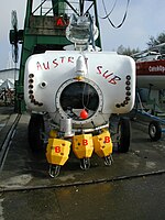 Figure 4a: Submersible with an LBL positioning system including baseline transponders (B) and submersible mounted interrogator (A).
 -
 Figure 4b: The submersible encounters one of the baseline transponders, now tethered above the sea floor.
 -
 Figure 4c: A float tube appears in the murky waters, indicating the gas pipeline - target of the survey - lies buried in the mud underneath.


Starting in the 1970's and continuing to the present offshore and inshore construction, in particular related to the oil & gas industry, became a major application for underwater positioning.[11] LBL system's combination of high positioning accuracy and reliability is in particular attractive for tasks such as high-quality seafloor surveys and the subsequent installation of drilling equipment. A typical example of LBL use related to underwater construction is the work of Austria Sub (figure 4a), a three-person manned submersible custom-built for underwater infrastructure inspections in the lakes of Austria such as Lake Constance.[12] When a storm caused a large vessel in the general area of an underwater gas pipeline to drag its anchor, authorities recognized the danger of a rupture and the fact that the exact position of the decades old pipeline was uncertain. Austria Sub was hired to re-survey the pipeline so that nautical maps could be updated. The job started with the deployment and survey of three baseline transponders in the general area of the pipeline run. Figure 4b shows Austria Sub encountering one of these transponders underwater. The LBL navigation system was programmed with a chart of the area including the assumed pipeline course, and Austria Sub started its dive - heading in a zigzag search pattern towards the assumed pipeline position. Before long, Austria Sub ran head-on into a partially collapsed float tube (figure 4c), confirmed by the LBL system to be almost exactly at the pipeline position indicated on the old chart. The pipeline, now buried deep under mud had been found. Equipped with an inductive sensor, Austria Sub started to follow the pipeline's course, using the LBL system to record precise positions as it proceeded.
LBL Systems Assist Divers
[edit]

By the mid 1990's, technology had been miniaturized sufficiently so that LBL systems became a practical tool for scientific and other diving applications. When NOAA commissioned the development of the AquaMap LBL system in 1994[13], it included a small diver terminal (figure 2) that allowed free-swimming SCUBA divers to navigate precisely, and electronically record observations with a positioning accuracy of around 0.3m [14]. AquaMap was first tested at the Aquarius Underwater Habitat, but soon it was adopted for other applications. By 2005, fisheries biologist Jeff Miller of the National Park Service had developed a formal protocol[15] and used AquaMap in conjunction with video recordings for several years to precisely map the growth and evolution of coral reefs in the U.S. Virgin Islands. LBL technology permitted finding specific coral heads without the need for physical markers, the presence of which can disturb the environment due to locally concentrating diver activity for example. When sea water temperatures rose slightly in 2005, it triggered a severe and widely reported episode of coral bleaching [16]. With a multi-year record for hundreds of LBL surveyed sample locations on hand, the NPS team was able to document the extent of the bleaching and resolve the critical question of cause-and-effect between coral bleaching and the onset of coral disease. [17]
LBL diver technology has continued to advance, and the DS-3 terminal (figure 5) includes graphic information similar to that of mapping GPS receivers.
LBL Positioning for In-Water Ship Hull Inspections and other Specialized Tasks
[edit]

The precision and robustness of LBL positioning results in part from the fact that the baseline transponders are mounted in the same frame of reference as the work being performed. But, while LBL systems are most commonly used for seafloor work, the concept is equally applicable to other reference frames. For example, in-water inspections of ship hulls are now common practice.[18] These may be conducted for example for maintenance purposes such as to verify the integrity of a hull, or security such as to check for ship hull mines (limpet mines) or contraband secured to a hull. In these cases, the baseline transponders can be mounted on the hull. As the ship moves, the baseline transponders move along with it, thus providing a stable reference frame. The AquaMap ShipHull LBL system relies on this approach, using four baseline transponders that are typically lowered over the side of a vessel, or attached to the hull with magnetic feet. The software provides port, starboard and bottom views indicating the current position of the inspection diver or ROV. As the inspection proceeds, the software paints the hull, drawing a black swath corresponding in width to visibility and indicating which areas have been visited. An inspection is complete once the entire hull is painted without or with acceptable gaps.
Manufacturers
[edit]Applied Acoustics (Transponders for LBL systems)
Desert Star Systems LLC (AquaMap LBL systems)
LinkQuest Inc. (Pinpoint LBL System)
Nautronix (NASNet LBL system)
Sonardyne (Fusion LBL system)
Sonatech (seafloor transponders)
Kongsberg Maritime LBL systems with MPT and cNODE transponders
References
[edit]- ^ Underwater Acoustic Positioning Systems, Chapter 4, P.H. Milne 1983, ISBN 0-87201-012-0
- ^ NOAA Diving Manual, Edition 4, Underwater Navigation, Section 10.2., ISBN 0941332705, 9780941332705
- ^ Handbook of Acoustics, Malcolm J. Crocker 1998, ISBN 047125293X, 9780471252931, page 462
- ^ The ROV Manual, Robert D. Christ and Robert L. Wernli Sr, Section 4.2.8. Capabilities and Limitations of Acoustic Positioning, ISBN 978-0-7506-8148-3
- ^ The ROV Manual, Section 4.2.6.4 Long Baseline (LBL)
- ^ LBL Underwater Positioning, Hydro International Magazine, Jan/Feb 2008, Volume 12, Number 1
- ^ Milne, Chapter 2
- ^ The Universe Below, Page 77, William J. Broad & Dimitry Schidlovski 1998, ISBN 0684838524, 9780684838526
- ^ History of Russian Underwater Acoustics, page 722. Oleg A. Godin, David R. Palmer, 2008, ISBN 9812568255, 9789812568250
- ^ MX Missile Basing, pages 173-175, 1981, ISBN 1428924507, 9781428924505
- ^ Milne, Chapter 1
- ^ Case Studies in Navigation & Positioning, Underwater Magazine, January/February 2002
- ^ DiveTracker: Characteristics and applications of an advanced dive mission control system, Flagg M., Oceans '95 Conference Proceedings, ISBN 0-933957-14-9
- ^ A GEODUCK (Panopea abrupta) Survey for the Brightwater Marine Outfall, Section 2.2.1, November 2002, Prepared for King County by Golder Associates Inc.
- ^ Using the AquaMap System at a Study Site, Monitoring Protocol, Jeff Miller, June 2002, US Dept. of the Interior, US Geological Survey
- ^ Corals Take Double Punch In Caribbean, New York Times, April 4, 2006
- ^ In Hot Water: Global Warming Takes a Toll on Coral Reefs, Environmental Health Perspectives, Volume 116, Number 7, July 2008
- ^ AquaMap Performance at HULSFEST, U.S. Navy Participant Report (excerpts)