
Talk:Capacitor/Archive 1
| This is an archive of past discussions. Do not edit the contents of this page. If you wish to start a new discussion or revive an old one, please do so on the current talk page. |
| Archive 1 | Archive 2 | Archive 3 | Archive 4 |
Wound capacitors seen as transmission lines
In light of the lengthy discussions on this page, it now should appear obvious to everyone that the transmission line (piece of coax) acts as a capacitor of simliar physical dimensions from the points of view of
a)energy storage, (CV^2/2)
b)impedance, (Z0 of line)
c)inductance, (zero )
e)equivalent series resistance, (Z0 of line)
- What is trivially obvious to me and probably to anyone else who is following this discussion is that if you construct two objects of similar dimensions and physical materials, you have two nearly identical objects. As you point out below, their electrical characteristics would also be nearly identical. I see this point to be self-evident. Is there something I'm missing here? Alfred Centauri 17:38, 15 September 2005 (UTC)
Wound capacitors have flat layers of conducting material either side of a dielectric. This sandwich is wound into a cylinder. THe terminations in the extended foil type are the overhanging edges of the foil. This therefore gives a transmssion line structure whose length is equal to the length of the rolled up cylinder. (a cm or two). It has been argued elsewhere on this page and not yet disproved, that a contra-fed transmission line acts in the same way as a normal transmission line as far as pulses and dc are concerned except that it can charge in half the time.Light current
- It will? I must have missed that argument. Please see my description of what I think will happen. Alfred Centauri 17:38, 15 September 2005 (UTC)
Yes. I just realised when writing this piece on wound capacitors, that a steady differential voltage of 2V appears all along the line in the one way travel time of the line (ie no reflections needed to establish the steady state) (I think!)--Light current 17:59, 15 September 2005 (UTC)
I think its obvious to us all now, but I dont think it was quite that obvious when I posed the question judging by all the posts that have been written.
Extracts from earlier posts on this subject:
No, they are not. How are they similar? — Omegatron 22:16, September 11, 2005 (UTC)
But we haven't agreed on your premise yet, LC, that the T-line is a capacitor....--Heron 12:59, 12 September 2005 (UTC)
I contend that an open-circuited (short-circuited) t-line is not equivalent to a capacitor (inductor). T.... Alfred Centauri 17:59, 13 September 2005 (UTC)
A t-line with the far end open-circuited is not equivalent to a capacitor at all.... Alfred Centauri 00:36, 13 September 2005 (UTC) NB the items in italics above are merely quotes from other posts and the other posts are still intact in their original order.--Light current 08:57, 18 September 2005 (UTC)
- LC - This is a correct statement. Why have you inserted it here (and out of context I might add) as if it were not? We have agreed that a physical capacitor constructed like a TL will behave like a physical TL constructed like a capacitor and that is all. The ideal capacitor exhibits only the property of capacitance. This is not true for the ideal open-circuited TL. Case closed. Alfred Centauri 21:33, 17 September 2005 (UTC)
Anyway, are we now all agreed that a short length of coax behaves like a small capacitor of similar length (apart from the fact that the value of the cable cap will be very small cf the manf cap)?--Light current 22:21, 15 September 2005 (UTC)
The wound extended foil capacitor can therefore be considered as a transmission line of length equal to the length of the capacitor's cylinder and of width equal to the total length of the winding. THe signal takes 30ps with air as the dielectric to traverse the length of a 1cm long capacitor. The dielectric constant of the dielectric material used will reduce the velocity of propagation in the capcitor. A contra fed capacitor will therefore fully charge from a pulse input in the one way travel time of the signal which, with low k materials, could be around 100ps. The inductance of this capacitor with its leads removed and properly mounted in a coaxial housing will approach zero. The ESR of this capacitor will be determined by the physical dimensions of the transmission line formed by its winding.--Light current 16:27, 15 September 2005 (UTC)
I was talking about capacitors not ideal capacitors. Case still open!--Light current 23:58, 17 September 2005 (UTC)
My insertion is merely a quote from one of your earlier posts. Surely you do not object to that? I was quoting it only because you said that you now believed a transmission line acted as a capacitor.--Light current 22:52, 17 September 2005 (UTC)
- I propose we do the experiment I outlined earlier today. Alfred Centauri 17:38, 15 September 2005 (UTC)
Yes. probaly best to use 300R twin feeder? I have to go out v. shortly, but I'll see if I can find some bits when I get home--Light current 17:49, 15 September 2005 (UTC)
- I do think twin-lead is the best choice as it should be quite easy to probe the voltage at points on the line by using insulation piercing probe leads. I do think it will be important to use a true differential probe when measuring the voltage across the line - grounding one side with the O'scope just wont do! Alfred Centauri 18:59, 15 September 2005 (UTC)
I think the setup would need to be matched to properly observe this effect, so this means a 50R to 300R balun. I have some 75R/300R baluns but im not sure of the effect of mismatch from my 50R gen to the balun i/p. Also a fiarly fast edge will be needed if a short length of cable is used. THe fastest rise I can produce/measure is about 1ns (at least thats what it looks like on my scope). I dont know the velocity factor of twin lead either but I guess were going to need quite a few feet to see much happening.--Light current 00:09, 16 September 2005 (UTC)
- Light travels 1 meter in about 3.3ns so 2 or 3 meters should be plenty. If my intuition is correct, the matching balun isn't going to do what you might think. Alfred Centauri 00:44, 16 September 2005 (UTC)
You could be right- we dont know whats going to happen but I was suggesting the balun partly to convert my unbalanced gen o/p to balanced. As to the matching, maybe its not important in the transient period. I dont think we can drive this 'thing' unbalanced--Light current 00:55, 16 September 2005 (UTC)
- Ahh! Good point! Alfred Centauri 01:14, 16 September 2005 (UTC)
VF twin 300R is 0.82--Light current 01:08, 16 September 2005 (UTC)
Im just stuck for a back to back 75R connector now!(I normally work with 50R) Ive got everything else ready , (having destroyed my FM radio aerial!) You havent got a spare you could lend me, have you?--Light current 16:55, 17 September 2005 (UTC)
- LC: You have reordered my replies so that they are now out of context. This is not acceptable to me. Please restore my comments in their original context. Alfred Centauri 22:24, 17 September 2005 (UTC)
I dont know your context. So please restore them yourself but without interupting my replies. Thank you!--Light current 22:27, 17 September 2005 (UTC)
- No sir. It is not the quoting that is unacceptable to me. It is the reordering of my comments in this article so that they are no longer in context. When I put my comments in-line, they are in context and you have not objected to this until just now. When you reorganized this article, you changed the discussion from what actually took place. That is, as they say, not cool. I hope you will reconsider you actions and take the corrective step that I have asked you to do. Alfred Centauri 23:58, 17 September 2005 (UTC)
As I said Alfred, I cant remember the order of comments that you made, except that they interrupted my replies. If would like to reorder them as you remember them, then please be my guest.--Light current 00:06, 18 September 2005 (UTC)
- You do not need to rely on your memory as you have the entire history of this discussion at your disposal. You have asked that I refrain from interjecting comments inline with your comments. I respect that and will oblige you in the future. However, such inline comments are not considered bad form on Wikipedia (as far I as can tell - please correct me if if I am mistaken) so my response is simply a matter of respect for your request. On the other hand, reordering the discussion so that a persons' comments are out of context is considered unacceptable behaviour on Wikipedia:
- "Don't misrepresent other people: As a rule, refrain from editing others' comments without their permission. Though it may appear helpful to correct typing errors, grammar, etc, please do not go out of your way to bring talk pages to publishing standards, since it's not terribly productive and will tend to irritate the users whose comments you are correcting. Certainly don't edit someone's words to change their meaning. Editing or deleting your own words is up to you. Also avoid putting others' comments in the wrong context"(emphasis is mine).
- Alfred Centauri 01:39, 18 September 2005 (UTC)
I was not intending to put your comments out of context. In trying to clean up the page and move your interjections so that they did not distrurb the flow and comprehensibility of my text, I may have erroneously put your comments in the wrong place. This is quite easy to do as the mark up text doesn't look exactly the same as the page. I had no intention whatsoever of trying to twist your words and if you feel I had then you are mistaken. However, if this has upset you, I would like to apologise once more. If we could keep the integrity of each others posts, then I feel it would be beneficial. After all, Ive missed quite a few of your additions because I did not find them until I was reviewing our discussions. --Light current 08:20, 18 September 2005 (UTC)
Fabry-Perot Resonator -- a capacitor for light?
copied from earlier post
What about a dielectric t-line? When I say dielectric t-line, think fiber optic cable. Alfred Centauri 03:34, 14 September 2005 (UTC)
3.Is it a capacitor?
4.Is there a charge current in a dielectric t-line?
Would anyone consider that the Fabry Perot resonator is a capacitor for light energy?--Light current 10:12, 17 September 2005 (UTC)
A Fabry-Perot resonator is a cavity formed by two mirrors on the same axis. Inside the cavity, two light waves can exist, one moving to the right, one moving to the left. The total field in the cavity is the sum of the two travelling waves. This sum is a standing wave pattern between the mirrors. For the standing waves to exist, L = m Lambda/2 where L is the length of the cavity and lambda is the wavelength in the cavity material, m is a positive integer.
If n is the refractive index of the material between the mirrors, the resonance frequencies of the resonator are given by f= mc/(2nL). THese are the longitudinal modes. The spacing between the longitudinal modes is deltaFc = c/(2Ln). This is very similar to an o/c transmssion line so I would consider in one respect at least (energy storage) that this device can act as a capacitor for light waves.--Light current 16:09, 17 September 2005 (UTC)
For a dielectric 'transmission line' such as a FO cable, then in order to achieve the analogous situation to step waveforms entering a TEM mode conducting TL or waveguide, requires the concept of an ultra broad band source of EM radiation extending from VHF up to Xrays (say). This is because a true step requires all frequencies up to infinity to be included. Such sources do not to my knowledge exist. Also to achieve the dc energy storage phenomenon as described for the TL capacitor, would require a dielectric material of ultra wide BW. Neither do these materials exist to my knowledge. In conclusion, because a dielectric wave guide is a narrow band device it cannot support all the frequencies necessary to mimic a capacitor. It can, however, mimic a capacitor as regards energy storage over its limited BW as in the Fabry-Perot resonator.
Bearing in mind the foregoing argument, answers to ACs questions 3&4 can now be given.
Q3 It is a capacitor in the sense that it can store energy.
Q4 There is no charge current in a dielectric T line as there are no movable charges.
- EM radiation contains energy in the magnetic field too. Since an inductor stores energy in a magnetic field, why not claim that a FO cable is an inductor also? Alfred Centauri 03:04, 18 September 2005 (UTC)
All in good time Alfred, all in good time!--Light current 07:50, 18 September 2005 (UTC)
I would just like to point out the the Fabry -Perot resonator stores its energy in the oscillating EM radiation not just in the electric or magnetic fields (maybe both at once!). Im really not sure if we can call resonator an inductor as there would have to be s/c ends to reflect the radiation. I dont know what a s/c end would look like unless it was a 180 phase shifting mirror. --Light current 18:33, 18 September 2005 (UTC)
Distinction between ideal components and physical components
Ideal circuit elements are used in circuit analysis. Thus, a resistor has resistance only. A capacitor has capacitance only. An inductor has inductance only. When we model non-ideal components, we combine ideal components, e.g., an inductor with a series resistance.
In circuit analysis, a capacitor is not an open circuited transmission line (TL). An inductor is not a short circuited TL, and a resistor is not a matched TL. This is because a TL is not a lumped element device. The analysis of TLs requires the full blown EM theory that circuit analysis ignores.
If full EM theory is used in the analysis of a physical circuit, we find that TLs are everywhere. The wire connecting one lead of a capacitor to a signal generator forms a TL with the other wire connected to the capacitor. A wire that is unconnected at one end is an antenna. There is radiation and there are reflections everywhere you look. This is not news to anyone (including myself) who has ever tried to get a product through EM compliance certification.
In this sense then, capacitors are TLs as are inductors, resistors, batteries, house wiring etc. etc. Everthing is a TL - Alfred is a TL - the vacuum is a TL. Heck, you don't even need conductors to have a TL. Bottom line, Maxwell's equations are valid everywhere. Thus, there is no such thing as pure capacitance, pure inductance or pure resistance. These are concepts that allow us to model physical devices so that we can actually solve and design electronic circuits and systems. When things don't quite work like we expect, it is often because we have ignored some EM effects that our model doesn't capture.
A TL is modeled with discrete ideal inductors, capacitors, and resistors. A TL is not equivalent to any one of the ideal components mentioned above. This statement is not in conflict with the statement that a physical capacitor, like any physical object, exhibits TL behaviour. Alfred Centauri 02:27, 18 September 2005 (UTC)
- Just a thought here. If capacitors act like o/c TLs of the same physical length (which I believe they do), then the modelling of TLs using capacitors is invalid. Also, the LC model for TLs gives a cutoff that is not actually present in the real line as I have confirmed when trying to SPICE tls. Be careful of trying to model TLs. TLs cannot be modelled by the LC representation. (unless you have an infinite number of infinitesimal value components and a rather large computer!)--Light current 08:44, 18 September 2005 (UTC)
LC: Please, please, PLEASE try to understand that when I say something is modeled with a capacitor, inductor, and or a resistor, I am referring to the ideal components. I know I have made this point numerous times. Why don't you get it? Circuit theory is based on ideal components. Non-idealities are modeled with additional ideal components. To model a TL in circuit analysis (which does not included EM effects), we MUST use lumped ideal components as an approximation. Why do you keep coming back to this? One more time. Circuit theory does not include EM effects. TLs can only be analyzed using EM theory. To use TLs in circuit theory, we must use ideal lumped components to model them. An open-circuited TL in circuit theory is not equivalent to a (ideal) capacitor - period - case closed. If you want to model a physical capacitor in circuit theory, then by all means, add ideal components to your hearts' content until it works like you want as long as you keep in mind, there are no EM effects in circuit theory. Alfred Centauri 01:24, 20 September 2005 (UTC)
- I agree that classical circuit analysis does not use EM theory. But if you just use cct analysis methods you get the wrong answers when looking at real components. Please refer to the links I have just added to the original question (for the benefit of new readers). You can't model a TL in cct theory by using ideal capacitors because of the false LPF effect you get with this method. Ive tried it on SPICE - it doesnt work unless you have thousands of very small inductors and capacitors. If you dont believe me, try modelling a TL on SPICE with Ls & Cs and see if you get the right anwers!Light current
- I, of course, totally agree that ideal components can only be represented by those self same ideal components. The discussion so far (from my side anyway) has been about real components and the best way to model them. Maybe I should have been more explicit in my original question. In general, because I'm more used to real components, unless I actually use the word ideal I mean real practical components. I apologise for not making myself totally clear at the outset. BTW, I am in no way suggesting that you teach your students to replace every ideal capacitor they see with a TL. That would be a silly suggestion on my part! But for practical, real capacitors -- well it I think a TL representation will give closer answers than the ideal representation especially at really high frequencies -- thats all Im saying. Light current 13:48, 20 September 2005 (UTC)
- Yes, if you were modeling it with discrete components you would need an infinite number of inductors and capacitors. To model it in SPICE you need to use the T or TLOSSY objects. — Omegatron 13:34, 20 September 2005 (UTC)
I just perused the links and what I see in these papers is that the physical capacitors referred to in the papers are modeled with cascaded lumped IDEAL elements including - you guessed it - capacitors. So, they are modeling a physical capacitor with capacitors (and other lumped elements). Doesn't that sound circular? Not to me. They are using IDEAL lumped elements to model the physical TL related effects. Alfred Centauri 02:52, 20 September 2005 (UTC)
Look at Figure 1(a) of the paper CAPpesc.pdf that you linked to. That looks a lot like our contrafeed thing doesn't it? Alfred Centauri 03:20, 20 September 2005 (UTC)
- It is indeed very similar. However, they are using the inductors in their model to represent the linking connections between the layers at each end of the cap. They are also using simple capacitors instead of TLs to model the actual capacitance between the layers so they wont get exactly the right answers.(Must have a word with Charlie 'bout that!) But it looks as tho' they're pretty close. Also the TL model thay are using will have a cutoff freq. It depends whether this cutoff is above their freq. range of interest or not. (must tell Charlie about that one too!) They only seem to be going up to 100MHz. Mind you, the ESR is not bad for a 100uF cap is it? :-)--Light current 03:49, 20 September 2005 (UTC)
- Ah yes, this is Omegatrons view also I believe!. What I am saying is that:
- a) a piece of o/c TL is indistingiushable from a capacitor of the same physical dimensions (if it was in a black box you could not tell the difference).
- b) the construction of most physical capacitors allows them to be considerd as pure transmission lines as I have illustrated at length in my previous posts. Im pretty sure the black box test results would apply here also.
- Just thought of good demo or practical test for students of electronics engineering/physics. Obtain a number of metal boxes with BNC connectors fitted. Inside some of the boxes wire small ceramic, metal film or multilayer capacitors of various (small pF) values. In other boxes, just wire one end of a number of short (< 100mm say) pieces of coax in parallel (10 - 20 would be a good number). Securely seal the boxes to make the interiors inaccessible to students! Dust off your network analyser(s) TDRs, vector voltmeters or whatever, and ask the students to tell you what's inside the (sealed) boxes. Ask them to tell you the impedance, ESR, ESL etc and deduce actually what is inside their particular box. Let me know if any correctly identify the transmission line boxes!--Light current 01:41, 20 September 2005 (UTC)
- BTW I have now completed the set up for the contra fed capacitor/TL. The results as yet are inconclusive. I may have a (low end) BW limitation on the balun that is causing some ringing. Also I am not able to match my 50R gen properly to the 75R balun i/p. Ive tried a 12dB 75 pad but thats no good. I need a 50 R pad but I ve got problems with the connectors not fitting at the moment!
--Light current 08:07, 18 September 2005 (UTC)
a) OK, identically constructed devices behave identically
b) OK, physical capacitors, like all physical components, exhibit TL related effects. BTW, have you considered the TL formed by the leads connecting the source to the cap?
c) I'm still working on performing this experiment on campus with some of the 'old' EM lab gear. I've also asked others to look at my 'analysis' of this thing. Alfred Centauri 01:31, 20 September 2005 (UTC)
- Always use capacitors with no leads whatsoever! (no leads -no inductance -no problem) BTW My results tend to indicate that your analysis was correct. ie theres no TL effect until the charge pulses meet!! :-)--Light current 02:09, 20 September 2005 (UTC)
Transmission Line 'Capacitor'
moved to talk transmission line
How does a capacitor actually 'charge up'?
Imagine an ideal current source connected across an empty (discharged) vacuum dielectric capacitor. Turn on the current source which acts as a pump for electric charge. The current source will merrily pump charge from the bottom plate to the top plate (say) and the voltage across the capacitor will ramp up. In this scenario, there are a couple of interesting questions.
1. Is any charge current actually passing between the plates.
2. Does anything pass or need to pass between the plates to allow the capacitor to charge? If so, what is it? --Light current 15:08, 19 September 2005 (UTC)
- 1. Some of the charges move from one plate to the other
- 2. Charge passes from one plate to the other to "allow" the capacitor to charge. — Omegatron 02:20, 20 September 2005 (UTC)
No I meant is there anything passing directly between the plates via the dielectric? If so, what?
- Just for kicks, imagine that the capactior is constructed thusly: Take some length of very large diameter solid wire. Make a very clean cut in the center (in the middle in between the ends) of this wire and move the cut sections apart ever so slightly. There is now an air gap between the cut ends. Connect your current source to the far ends of the wire. The changing charge density on the cut ends will now be uniform across the face of the cuts. That is, there is no current parallel to the face of the cut ends.
- A(1) No, there is no charge current passing between the cut ends (until the E-field is strong enough to pull electrons off of the surface of the metal).
- A(2) Yes, something passes between the plates. It must. Think of it this way. An electron is moving along the conductor until the cut end is reached and it then must stop. The 'information' that the electron has stopped must pass across the plates. How do you think this information is passed across the plates? Alfred Centauri 03:08, 20 September 2005 (UTC)
The information that there is charge build up on one of the plates is communicated to the other plate by the electrostatic repulsion of similar charge carriers in the other plate. So they get pushed down the wire. Yes?? So what passes between the plates is information in the electric field?--Light current 03:17, 20 September 2005 (UTC)
- Ah. Depends how you define "something", I guess. — Omegatron 05:09, 20 September 2005 (UTC)
Exactly, O, but what AC and I are trying to establish here is the necessity (or not) of displacement current in capacitors. He say YO! (probably), I say -- dont know!. So we're just working thro the argument step by step. Any insights you have along the way would be interesting.--Light current 12:25, 20 September 2005 (UTC)
- The electric field associated with the electric charge on an electron permeates all space so clearly the electric field passes between the plates but I'm looking for something else here. We know that when charge is moving (from our perspective), there is also magnetic field present. What happens when the motion of charge changes? That is, if you picture the charge as smoothly flowing down the wire but suddenly stopping at the cut end, what must happen to the field of a charge that is suddenly stopped? Alfred Centauri 13:51, 20 September 2005 (UTC)
Are you trying to say that the magnetic field, if it existed in the (open circuit from a low freq POV) system would then collapse?
- On the contrary, when the electric charge suddenly stops, The 'information' that the charge has stopped propagates in every direction at some finite speed. This 'information' is in fact a sudden change in the electric field perpendicular to the line of sight to the charge. Accompanying this sudden change in the electric field is a sudden change in the magnetic field that is perpendicular to the change in the electric field and to the line of sight to the charge. What do we call this 'information'? Alfred Centauri 14:49, 20 September 2005 (UTC)
Im going to think about this very carefully before I answer.--Light current 15:03, 20 September 2005 (UTC)
Let me get you straight. Are you saying that as each new 'electron' or packet of charge reaches the top plate, then the electric field between the plates jumps up a bit? Is so I would agree. Is this your sudden change in electric field?--Light current 15:21, 20 September 2005 (UTC)
- When electric charge is accelerated, there is EM radiation - the information. However, I was misleading in what I wrote earlier since the radiation along the line of the acceleration is zero and is maximum perpendicular to the accleration. I'm still working this 'picture' out so I'll return with more comments later. Alfred Centauri 20:16, 20 September 2005 (UTC)
I think I see what you may be getting at. As the charge difference builds up on the plates, an increasing electric field is produced between them. According to old J.C. Maxwell, a changing electric field here produces a magnetic field that is propagated into space at the speed of light outward from the capacitor plates and with the changing electric field you get some EM radiation.(traveling magnetic waves cannot exist alone - can they?) Now I think E x H gives the direction of the radiation and this would appear to be radial from an axis perpendicularly joining the centres of the capacitor plates, Yes? So nothing is actually passing between the plates yet then?
But heres an interesting thought: Assume that this radiation is indeed radial and assume we have a circular parallel plate capacitor. Also assume that this radiation starts from the centre of the capacitor (where else could it start?) When the travelling EM wave reaches the periphery of the capacitor discs it sees an *open circuit* so what happens to it? ;-)--Light current 15:46, 21 September 2005 (UTC)
- "a changing electric field here produces a magnetic field that is propagated into space at the speed of light...". That's almost correct. Recall that the wave equations for E and H involve the field and its second derivative with respect to time. Thus, an E or H field that is steadily changing does not propagate as an EM wave. A steadily changing uniform electric field between the plates of a capacitor is not associated with an EM wave since the second time derivative is, in this case, zero. The angle I'm working on is the effect of the radiation that must come from the deceleration of flowing charge at the cut face of the wire. Alfred Centauri 12:45, 23 September 2005 (UTC)
Let me try to offer some suggestions here. It seems you are having trouble because your second differetial of E is zero. Right? However, the charge flow cannot start infinitely slowly. Neither can it end infinitely slowly. So there will be a non zero 2nd diffl at the the start and end of the charging period, does that help at all?--Light current 22:43, 26 September 2005 (UTC)
- At this point, I'm not assuming a transient current - I'm assuming the current is steady. If a current enters a volume of space but does not exit, the flow of charge must stop somewhere inside the volume. This implies that charge has decelerated which implies radiation. It seems reasonable to me that, for a constant current, this radiation is constant over time. What is the magnetic field associated with this radiation? Is this magnetic field identical to what is associated with the displacement current term? These are the questions I'm attempting to find the answer to. Alfred Centauri 23:03, 26 September 2005 (UTC)
Yes, I understand what you are trying to do now. THe radiation maybe constant but IMHO it cant escape the interior of the capacitor because it sees an o/c at the ends. Do you agree with me on that one?--Light current 23:21, 26 September 2005 (UTC)
- I'm referring to radiation into free space, not a TL guided wave. When an electron stops (or starts) moving, there is radiation. Imagine pushing a constant current into a long wire (open at the far end) strung across your back yard. What does the electric and magnetic field look like at the far end? Alfred Centauri 02:56, 27 September 2005 (UTC)
- Hmm, this is weird. I'm not sure if we should be thinking about the electrons decelerating here; perhaps the effect is negligable because there is so little actual movement of electrons with a reasonable current. I'm not denying that electrons radiate when they change velocity, but... Consider a wire bent at a right angle, with a constant current. The electrons change direction at the bend, but they don't radiate, right? Perhaps a small amount that is negligable. Even in a straight wire, the electrons don't move in straight lines; they are constantly colliding with nuclei, which produces resistance. But a straight wire doesn't radiate.
- My understanding from electrodynamics is that a constant current produces no radiation. I don't know how to reconcile that with the above.
- Another thing to consider is that the current doesn't actually go all the way to the end of the capacitor. That is an oversimplified picture, even from a classical standpoint. To raise one end of the capacitor (and its associated wire) to a particular potential, there must be additional charges deposited along the whole surface of the capacitor plate, on both sides, and on its associated wire. (Because an increased potential creates an increased normal electric field at the conductor, and the charge at the surface of a conductor is proportional to the normal electric field.) So the actual current gets less and less as you go down the wire towards the capacitor plate. Pfalstad 16:14, 2 October 2005 (UTC)
- If velocity changes rapidly, the acceleration is large. If the electron is instantaneously stopped, the acceleration is an impulse. You say that a straight wire doesn't radiate. What if a constant current is pumped into a long wire that is open at the far end?
- Ok, I'll give that a try. All I could find on the net about the thickness of the charge layer is that it's a "few molecules thick". Well the lattice spacing is about 4 angstroms, so let's say 20 angstroms. Let's say the charges go at a constant 3 mm/s rate down the wire until they get to the last 20 angstroms, and then decelerate at a constant rate to reach 0 velocity at the end. I came up with a deceleration of 2250 m/s^2 for 1.33 microseconds. Use the Larmor formula, multiply by the number of electrons in that last 20 angstroms using the same numbers as before, and you get 2.6 x 10^-33 watts. That's for a 20 amp current flowing into a dead end. Pfalstad 02:30, 3 October 2005 (UTC)
- I just found in Jackson that the thickness of the charge layer is 4 angstroms, which means a larger acceleration, but the result is still miniscule: 1.3 x 10^-32 watts. Pfalstad 18:43, 3 October 2005 (UTC)
- I can't agree with your statements in your last paragraph. If, as you say, the current through the wire is proportional to the distance from the plate, the charge density must be in proportion to the distance from the plate. That is, the further from the plate, the greater the charge density. Not only does this seem ludicrous but such a charge density distribution would act to increase the current until it were uniform along the wire. Alfred Centauri 00:20, 3 October 2005 (UTC)
- No, it's not proportional to the distance from the plate. The charge density decreases as you go away from the plate; the current increases. But not proportionally. Just monotonically. Hard to explain. Try [1] and select "Setup: Sharp Point". This is an electrostatic case; the yellow represents charge. It is concentrated at the point, but it is still present below the point. Also try [2] and select "Setup: Capacitor". The arrows represent current; the yellow and blue represent charge. It's a capacitor confined in a box, so it's not a great example, but it's something. Pfalstad 02:30, 3 October 2005 (UTC)
- What is my point here is that what you have said (again) violates conservation of charge. Consider some volume defined by the cylindrical surface of the wire and two points along the wire and a current towards the plate. If the current increases as you go away from the plate, The current entering the volume must be greater than the current leaving the volume. Thus, charge accumulates within the volume. This implies that the charge density increases as you go away from the plate. Alfred Centauri 10:21, 3 October 2005 (UTC)
- OK, so that's not entirely correct. Assume the current density along the wire is proportional to some postive power n of the distance x from the plate and is in the direction of the plate. The time rate of change of the charge density is the negative of the divergence of the current density which, in this case, is just the derivative w.r.t. x. If n = 1, the charge density along the wire increases uniformly with time along the wire. If n > 1, the charge density increases faster further out from the plate. If n < 1, the charge density increases faster closer in to the plate. Thus, with this qualification of n < 1, your statement does not violate conservation of charge as I originally claimed.
- However, something still doesn't 'feel' right. The charge in a conductor, being free to move, will assume a configuration that minimizes the potential energy. My intuition tells me that the lowest energy configuration is when the excess electrons on one plate are as close as possible to the positive ions on the other plate. Thus, in the static case, it would seem reasonable that the charge distribution should be uniform over the inner surface of the plates. Alfred Centauri 15:34, 3 October 2005 (UTC)
- Any conductor at nonzero potential has charge on its surface. To see this, consider that the electric field just outside a conductor is nonzero if its potential is not zero. This must be true, since the electric field is the negative gradient of the potential, which decreases as you move off the conductor towards ground. The field is also perpendicular to the surface, and inside the surface, the field is zero. So use gauss's law to integrate over a small volume straddling the surface. The part of the surface perpendicular to the surface, and the part inside, does not contribute to the integral; only the part outside contributes, giving a nonzero value, which means that there must be charge enclosed in the surface. So there is charge on any non-grounded conductor, including the back of the capacitor plates as well as the leads and the wires attached. Of course most of the charge is concentrated on the inner surface of the plates, but even there it is not 100% uniform; it's slightly weaker near the edges. Pfalstad 18:36, 3 October 2005 (UTC)
- I agree with the above for an isolated conductor but here, we are considering two oppositely charged plates in close proximity. In the limit, we have two parallel conducting planes that are infinite in extent and with equal but opposite surface charge density. In this case, the electric field outside these planes is zero. Consider the 'model' capacitor with two parallel circular disks in close proximity where the separation distance is much smaller than the radius of the plates. The leads of this capacitor are connected to the center of the disks. The electric field in the vicinity of this connection should be essentially zero becoming exactly zero in the limit as the radius goes to infinity. Alfred Centauri 01:21, 4 October 2005 (UTC)
- Well of course if they have infinite extent the field is zero. But I disagree the electric field is "essentially zero" in the finite case. It is certainly very small in comparison to the field between the plates. Whatever, I only mentioned it because I thought it would help resolve the electron deceleration problem, but now that's not necessary. (In my mind anyway.) Pfalstad 15:19, 4 October 2005 (UTC)
- Ok now I'm sure that we can neglect the accleration of electrons in conductors. I don't know how to calculate the power radiated by electrons in a capacitor, since I don't know how fast they decelerate. But take a simpler example of current moving in a tight circle, 1 cm radius. Certainly these electrons are accelerating and therefore radiating. Let's say we have a 20 A current in the circle, using a 1 mm diameter wire of silver (which has 5.8*10^28 free electrons/m^3). Using I = nqvA (n = electron density, q = electron charge, A = cross-sectional area of conductor) we get a drift velocity of 3 mm/s; pretty slow. a = v^2/r = .9 mm/s^2. Calculating the rough volume of the conductor, we get 1.2*10^36 free electrons in it. The Larmor formula gives us the power radiated by one electron, and multiplying this by the number of electrons, we get 5.6*10^-34 watts of power radiated, which we can safely ignore. Pfalstad 17:33, 2 October 2005 (UTC)
- What you have shown is that we can neglect the loss of energy due to radiation in your example. Are you convinced that your example is sufficient to prove that the magnetic field associated with the sudden deceleration of charge due to the termination of a current within some volume is negligible? Alfred Centauri 00:20, 3 October 2005 (UTC)
- Yes, see above. Pfalstad 18:36, 3 October 2005 (UTC)
- Very well, when I am finished with my analysis, I may come to the same conclusion but I'm not convinced just yet. Regardless, I hope to gain some additional insight along the way. Alfred Centauri 01:24, 4 October 2005 (UTC)
- How about this: let's assume that when the electrons reach the end of a wire, all their kinetic energy is instantly converted into radiation. Since I = dQ/dt, the number of electrons hitting the end is I/e. I=nevA, so I/e = nvA. The total power released is nvA * (mv^2/2) or Imv^2/2e. For a 20 A current that's 5 x 10^-16 watts. Pfalstad 20:39, 5 October 2005 (UTC)
- Oh dear, I think my previous analysis (where I used the Larmor formula) was wrong. I don't think you can just take the power from the larmor formula and multiply by the number of electrons, because the larmor formula has an e^2 term. Multiplying the number of particles by n causes the field to be n times larger, which makes the power n^2 times larger. If I correct for this (by multiplying by the square of the # of electrons, instead of the number of electrons), I still get something on the order of 10^-19 watts. My analysis above using kinetic energy is correct, I think. Let me know what you come up with, AC. Pfalstad 01:59, 6 October 2005 (UTC)
Not Displacement current
Just a simple question here. Are you both sure that charges in the wire or on the plates come to rest very quickly? Or do they slow down gradually as they meet more of thier friends? (electr static repulsion). I suggest that the only thing going fast here is the EM energy (parallel to the plates of the capacitor). It travels at the speed of light in the medium. There is minimal effect due to charges decelerating because they're not travelling very fast in the first instance!--Light current 00:46, 5 October 2005 (UTC)
- While I do not yet know the answer to the question of the manner in which the charges decelerate, I do wish to point out that the inititial velocity of the charge can be very small whilst the deceleration can be arbitrarily large. Here's another consideration. As you point out, EM energy propagates at the speed of light in the medium. For a transmission line made from conductive plates or wires or what not, there is a current associated with this EM wave. Now, we all know that the electrons are not moving at the speed of light. What is moving with the EM energy is a charge density wave. Consider the implication of this. For the charge density to increase, the electron density must increase so the electrons must move closer together. What is the acceleration associated with this? Alfred Centauri 01:19, 5 October 2005 (UTC)
No. The whole point of this discussion is to show (hopefully) that no charge needs to move to get EM radiation. That this is so only requires consideration of EM propagation in vacuo.--Light current 01:24, 5 October 2005 (UTC)
Also, I can't see how you can get very high time rates of change of charge density if you dont have the actual charges moving at the same high rates (even at the (sub)atomic scale). I also notice that you have sneaked the concept of displacement current back into the argument. This has not been proven to exist. In short, I think there is no cat up your tree!(Woof! Woof!) [3]--Light current 01:36, 5 October 2005 (UTC)
- You must have read some other post than mine because I don't see anything in there about displacement current nor did I intend for anything to be in there about displacement current. Perhaps you aren't sure what displacement current is defined to be? Also, you seem to be confused about particle density and particle motion. Try reading about sound waves. Finally, EM radiation must have a source. Although EM waves propagate in vacuo, something must have created the disturbance in the first place. That disturbance is, in classical EM, none other than accelerated charge. Alfred Centauri 03:16, 5 October 2005 (UTC)
If charge cannot move at 'c', what is your mechanism for the actual charge density wave to propagate at 'c'. You are trying to find a mechanism for how ordinary current (the slow movement of charge carriers) converts into EM radiation. It cannot directly be due to the acceleration of the charge carriers as has been calculated by Pfalsted. Therefore there must be another process. (Unless of course the EM energy is already there in another guise, like dc? Refer to my original question about diff between EM and dc)--Light current 15:07, 5 October 2005 (UTC)
- To answer your first question, please see the link that Pfalstad points to below. Your second statement is incorrect - I know how a changing current produces EM radiation and Pfalsted and I agree (I think) about this. The question I raised at the begining of this entire discussion was this: when an otherwise steady current terminates in some volume of space, what is the magnetic field due to the radiation of the decelerated charge within the volume. My hope is that there is some simple relationship between the magnitude of the current into the volume and the deceleration associated with the termination of the current. Regarding your last question - EM what? dc what? Alfred Centauri 16:38, 5 October 2005 (UTC)
You definitely need movement of charge to get radiation. Pfalstad
Where does this moving 'charge' come from in a vacuum borne EM wave? Are you just talking about the initial generation of that wave in a conductor system? Propagation of Electromagnetic waves doesnt involve charges moving does it?. If you are talking about the generation of EM waves in an aerial system, this seems to be what AC is talking about (as far as I can tell) and this seems to be what AC is trying to work out. i, on the other hand, do not offer any explanation of How charge current is converted to EM radiation. My suggestion is that the EM radiatiopn and actual charge current are (almost totally) independent of each other. Take a battery, and a parallel pair of wires connecting the terminals to a load resistor via a switch. We know that the energy travels at'c' but the charges travel much more slowly. You will probably say: Ah yes-- but the charge density wave travels at 'c'.In that case, I must repeat my earlier question which was: what is your mechanism for describing light speed travel of charge density? Or to put it another way, what is it actually that travels at light speed to cause these fluctuations in the charge density on the wire. The answer of course can be only one thing: EM radiation flowing between the wires (not in them) --Light current 21:25, 5 October 2005 (UTC)
- We are talking about the initial generation of the wave. EM wave propagation does not involve moving charges.
- I think the EM fields that surround the wires is what travels at light speed to push the electrons along. At least this guy seems to think so: [4] Pfalstad 23:08, 5 October 2005 (UTC)
Ah.my dear Pfalstad. Yes. I agree with the above post of yours. What Ive been trying to explian to Alfred (not very sucessfully) is that it is the EM wave that is fundamental and the current, mag field etc are all a result of that. I suppose you could say that the EM wave drags along the charges as fast as they will go. When a capacitor is charging slowly is when I have a slight problem because I cant see the mechanism by which 1 electron per half hour say arriving at the top plate can give rise to all the effects that Alfred seeks especially when you have both almost agreed that the electron deceleration can give only a tiny amount of radiated power. The only possible solution I can see is that each electron, as it arrives, is accompanied by a tiny amount of EM radiation (which has actually dragged it along). This radiation flows into the top plate and sets up a standing wave of very small amplitude travelling from one end of the plates to the other end and back again.. As more and more electrons arrive,(againg accompnied by their associated EM energy) the standing wave amplitude in the capacitor slowly builds (in a linear manner if current fed). Of course, if the EM adds non coherently (out of phase) in the transmission line between the capacitor plates, the voltage produced across the plates will show some noise (if you had anything sensistive enough to see it).I'm not sure whether it does or not. I would be interested to know what you think of this suggestion.--Light current 23:57, 5 October 2005 (UTC)
- LC - I don't recall you trying to explain this notion of yours to me at any time but regardless, I disagree with the statement that the EM wave is fundamental and the current and magnetic field etc are all a result of it. The notion that the EM wave drags the charges as fast as they will go is ludicrous. Look at the direction of the electric field lines associated with an EM wave propagating along a transmission line. They electric field lines are transverse to the motion of the charge. Now, think carefully, what is the direction of the force on an electric charge in the presence of an electric field? OK, now look at the magnetic field lines which are also transverse to the motion of the charge and perpendicular to the electric field. Now, once again think carefully, what is the direction of the force on an electric charge moving in a magnetic field? Do you see now? The force on the electric charges due to the propagating EM wave is not in the direction of the current in the conductors of the TL so you'll need to explain (I know, I know - you've tried many times but please try again) to me how this idea of yours works. Alfred Centauri 01:22, 6 October 2005 (UTC)
Please dont call my ideas ludicrous. If you think they are wrong, disprove them. My previous statement about charges being dragged along was very sloppy (made without due thought)and I retract it. The charges in the conductors are induced in the surface of the conductors and therefore dont need to move along the wire in the direction of the energy vector. So do charges play any part in energy transfer at all? If you are preparerd to listen to my arguments without trying to score points or deride my attemts at explanation, imply I'm a crank etc, I will be happy to try to explain my viewpoint. Whether you or others agree is up to you/them. But if not, it will be incumbent upon those persons to demolish my arguments one by one not just try to dismiss them as cranky thoughts--Light current 19:26, 8 October 2005 (UTC)
moved to talk:transmission line
Chapter 4 Hand waving
Im not going to go as far as saying an electron is ONLY an EM wave. As we have established earlier, it seems no one knows exactly of what an electron consists. However, certain of its attributes may be explainable in terms of EM waves.--Light current 16:53, 13 October 2005 (UTC)
We still have something of a paradox here. We know for instance in a real TL travelling waves produce losses due to skin effect, but in a situation we have just described, we find zero or very low losses. Can you say why?.
- Yes, I can; it's because your model is wrong. In a lossy TL, using this model, losses would damp out the waves you just described very quickly; but a real TL maintains its charge, once charged (except for leakage currents through the dielectric, ionized air, etc). Also, in a lossy TL, dispersion would mess up the nice square edge of the waves, so that they wouldn't line up nicely anymore and would no longer add up to flat DC. This shows that you cannot accurately model a charged TL as a combination of traveling waves. Pfalstad 18:40, 12 October 2005 (UTC)
Well I say my model is correct. The reason there are no losses is that there is no net current. This therefore lines up with the actual situation of a charged TL.--Light current 03:15, 13 October 2005 (UTC)
Sorry, but that violates the very principle of superposition that you idea hinges on. You claim that the steady state voltage on the line is the result of the superposition of traveling waves. For consistency, you must also superpose the currents associated with the traveling waves.Even if the resultant current is zero, the power loss to the resistance in the conductors of the TL will be non-zero. That is because power in a resistance is non-linear in the current.I'm wrong - you must take the superposition sum before calculating power just as you stated. Alfred Centauri 14:36, 13 October 2005 (UTC)
However, the importance of this apparent duality of EM waves and steady dc, in my mind, cannot be underestimated. It should have impressed you also, although you seem remarkably blase about it!. If the duality is accepted, it has far reaching consequences on the nature of those things we call voltage and current. I will leave the idea with you a little longer before suggesting applications and ramifications of this duality idea.--Light current 17:47, 12 October 2005 (UTC)
BTW, if you had been taught this idea at university, college, would you have believed it?--Light current 18:11, 12 October 2005 (UTC)
- I think I would have asked the same questions, especially, "what's the point?" Pfalstad 18:40, 12 October 2005 (UTC)
Sorry, I thought I had described what the point was. Obviously you do not wish to accept the implications.--Light current 01:57, 13 October 2005 (UTC)
- Don't keep us in suspense. What are the implications? Pfalstad 03:34, 13 October 2005 (UTC)
OK heres one. Is a simple battery a source of dc only, or is it also a source of EM radiation. Please think crefully before answering! ;-)--Light current 17:10, 13 October 2005 (UTC)
Heres some more thoughts. What function do the charges on the transmission line conductors have in the transmission of the EM energy back and forth in the line. Do they need to be mobile carriers? Do they need to move?. Do they need to be there at all.? I think I can answer these questions, but I leave it to you or AC to comment first --Light current 17:37, 13 October 2005 (UTC)
- Well any source of DC has to create some small amount of radiation when starting or stopping a current. I wouldn't consider it a source of radiation though. The radiation is just a side effect of the changing current. The charges in a TL need to be present and mobile. You seem to be minimizing the role of electrons. There are many effects such as the photoelectric effect, vacuum tube behavior, the effect of temperature on resistance, the Millikan oil drop experiment, etc. which require electrons to explain. Whereas these counter-propagating waves you postulate don't seem to have any measureable effects at all. Pfalstad 16:19, 16 October 2005 (UTC)
Of course, one would normally say that a battery is not a source of EM radiation at all. However if steady dc can be represented as counter propagating waves then one must ask the question. THe reasons you give for the necessity of mobile charge carriers in the TL are not logical. For instance, its possible to have charge separation in a dilectric is it not? Im not saying electrons dont exist! Your last sentence, maybe, highlights the difficulty with the idea: ie if these waves cannot be distinguished from steady dc, what does that mean?
- What are you saying about electrons then.. They exist, but don't move? They don't move in TL's? TL's would work even if they didn't move? If conductors don't have mobile charge carriers, why do conductors reflect EM waves? Dielectrics aren't really a comparison because they reflect EM waves very weakly. Quantum mechanics can show that conductors have band structures that enables electrons to easily move. Dielectrics don't. Pfalstad 21:16, 16 October 2005 (UTC)
There are a few conclusions one could draw.
a) a transverse electrostatic field in a TL CAN be generated by an initial one way flow of energy as when charging, and then maintained by the counter propagating EM waves. (showing some equivalence between EM and dc.)
OR b)travelling EM waves do not exist in the TL at any time. So how does the energy get there?
OR c) travelling waves are initially used to charge the capacitor but when charged, the waves stop moving suddenly. But how do they do that? ie what is the exact mechanism by which they are stopped- and stopped instantaneously at that?
- I vote (c), although I only consider the leading edge (the changing part) to be a wave. Pfalstad 20:46, 16 October 2005 (UTC)
AS I said before, things that cannot be distinguished as different my any method whatsoever might as well be considered the same. Whether they are truly the same or not is a philosophical question, not one of physics.--Light current 17:17, 16 October 2005 (UTC)
- It sounds like you are proposing a different interpretation of the physics rather than new physics, right? Well I suppose you're welcome to do that. If it can't be falsified by experiments, it's just an interpretation. I don't find it compelling personally. But if you like it, great. Pfalstad 20:46, 16 October 2005 (UTC)
- Someone appears to have forgotten or has chosen to ignore one crucial aspect of EM waves - the electric field associated with an EM wave in free space is non-conservative. The steady voltage on the TL in the example above can only be created by a conservative field - a field created by the differing charge densities on the conductors of the TL. Alfred Centauri 20:45, 12 October 2005 (UTC)
Could you say what you mean by that in plain English please?--Light current 01:53, 13 October 2005 (UTC)
The fields we are considering are not in free space, the electric field exists between the two conductors. I didnt say anything about the charge densities on the conductors. AC I dont think your above statement says a great deal. We have a steady (dc) electric field. But we also have two counter propagting ac waves that have been show to add up to the dc version. Does this worry you at all?--Light current 16:17, 13 October 2005 (UTC)
Chapter 5
You haven't shown anything as far as I am concerned. You have made some hand-waving arguments that aren't very good and you believe that you to have shown something? Do you consider this rigorous? Please show mathematically what you claim to be shown. Do you agree that the electric field between the conductors of the charged TL is due to the net electric charge on the conductors? The conservative part of the electric field is, by Gauss's law, due to electric charge. The non-conservative part of the field is due to changing magnetic flux. Potential difference (voltage) has meaning only for a conservative field. The voltage across the conductors of the charged TL must be due to a conservative field. This field can only be created by electric charge. Alfred Centauri 17:44, 13 October 2005 (UTC)
- I reply to your points one by one, but outside the body of your post so that the threads do not become entagnled.
- Point one: I do not consider my argument to be rigorous. It would require a lot more math to do that and convince you. So I leave that to persons more skilled in the art than I. Maybe you could indicate to me your required standard of mathematical rigour? What I have shown is, that by simple application of known facts and a little bit of logic, you can get dc from two counter propagating EM waves. Or do you still dispute that? With your skills in field theory and vector calculus it should be a simple matter for you to show me that these simple ideas are wrong. (But please try to keep your proof simple so we can all understand it)
- Point two: I agree that there is an electric field between the two conductors. What its due to has yet to be established but its measureable effect is an imbalance of charge betweeen the 2 conductors. What part in the EM propagation does this charge play if any?
- Point three: I cant really see what your point is here. There is no resultant changing magnetic flux therfore according to your statement, no non-conservative field. THere is a net conservative field because again according to your statement which I take to be correct, there is a net charge imbalance. Whats the problem here? I dont see it. :Are you saying that extra charge from outside the system must be introduced in order to charge the line? I thought we had dismissed that one on the capacitor page many moons ago.
- I would be grateful if everyone could follow my convention, and reply outside the body of my posts. It gets far too tangled when people dont. Thanks.--Light current 22:43, 13 October 2005 (UTC)
- AC that is a good point; he shouldn't be able to combine waves in this way at all. There must be net charge in the TL for this to work, by Gauss's law, not just waves. I'll bet the two waves do not add up to DC at all. If I knew more about TLs, and/or cared to bother, I would go work out the details of what the wave looks like and what it adds up to. Perhaps you can? Pfalstad 03:34, 13 October 2005 (UTC)
- Not a net charge Pfalstad, but a charge separation. The only thing stored in the line is energy. Does that make any difference to your objection? THe two waves obviously add to dc. Its a charged capacitor after all! You probably know all you need to know about TLs to think about these questions. AS I said before, its about thinking, not about applying complex vector calculus.--Light current 17:02, 13 October 2005 (UTC)
- Right, right, no net charge. Never mind the Gauss's law. It's not obvious that the two waves add up to DC. It's obvious that there's DC, it's not obvious that this DC is composed of two waves. Pfalstad 21:39, 15 October 2005 (UTC)
I am trying to find a way of explianing this waveform thing mathematically using Heaviside functions. But I need to do some research first.--Light current 21:43, 15 October 2005 (UTC)
Disconnection of the generator
Since this aspect seems to be causing a lot of controversy with regard to the validity of my arguments on the transmission line circuit, I am going to try to answer all the points opn this aspect that have been made. To do this I must go back and review all the posts (mainly from AC) so I know exaactly what the objections and comments are. I therefore hope that AC and other interseted perties will bear with me whilst I do this revision and compose a reply. Thank you for your patience.--Light current 01:30, 14 October 2005 (UTC)
By studying some of your earlier posts on the generator problem AC, Maybe I can cut short the discourse by saying the following:
Let the generator remain connected for all time after the initial connection. At the time of arrival of the reflected wave front, there is 2V from the gen, and 2V on the line. Now what is the current thro Rs (the generator source resistance)? Zero!. So from the point of view of the wave, what impedance does it see? Infinity. So what does that mean? Is it a short, open or matched?
- The impedance is R, because the resistance is R. The resistance of a resistor does not change if there is no current across it. Let me put it this way. How could we test what the impedance is? If the impedance were R, 0, or infinity, what would be the result in each case? Pfalstad 05:44, 16 October 2005 (UTC)
The resistance of a resistor is still the same if its in the drawer, but that doesnt mean it has any effect. Think of bootstrapping. Actually, come to think of it, it doesnt really matter what the impedance is after the lines charged as long as the gens still connected. It could be zero, 50ohms of infinity as far as the signal is concerned. Thats because no current can flow thro this resitor. So it can be defined as anything you like. But its not connected to ground - its connected to 2V. The wave incident at this resistor cant push any current thro it. (cos theres 2V on the other side. The wave couldnt push any current thro an o/c if that was there instead could it?. So as far as the wave's concerned, it might as well be an o/c. Also, this must be true, otherwise the wave would pass current thro the resistor and the reflection would be less than it actually is. THat would mean there would not be 2V on the line after 2T. Can you see it now? I dont think there are many other ways to explain it. T
The standard way of testing the impedance is to look at the reflected signal. rho = (Zl-Zo)/(Zo+Zl) where rho is the reflection coefficient.(reflected ampl /incident ampl), Zl is the load resistor. In our case, rho=+1 (all refelected with no inversion), yes?- so you can work out Zl for yourself.--Light current 06:36, 16 October 2005 (UTC)
- According to this applet you showed me, [5], if you set the source impedance to 25, the load R to 99999, and click start, you get a reflection at the right end, and then the wave comes back and stops, with no reflection. Is that applet wrong? What do you think happens? Pfalstad 14:37, 16 October 2005 (UTC)
No. The applet is completely correct. Thats what I ve been saying all this time. THe applet shows the total voltage on the line which is made up up of the sum of each traveling wave. (V+V=2V). I shows the two travleing waves add to give dc! BTW a TL can have a waves travelling in both diections simultaneously but Im sure you knew that.--Light current 19:07, 16 October 2005 (UTC)
- That's one way to look at it. I prefer to view it like this: a wave (by which I mean the changing part, not the steady DC field) goes out, is reflected, comes back, and is absorbed by the source termination. Pfalstad 20:56, 16 October 2005 (UTC)
I know thats the way you prefer, but its not correct because energy is still flowing behind the wave front. That this is so can be seen because until the reflected wave reaches the near end again, energy is still being pumped in to the line from the generator and all waves are travelling!--Light current 21:09, 16 October 2005 (UTC)
- It's not just the way I prefer, it's the standard way this is taught. Is everyone doing it incorrectly except you? Anyway, that's fine, energy is being pumped into the line. This is the energy necessary to charge the line. Like a capacitor, CV^2/2. Once it's charged, the energy flow stops. Pfalstad 21:26, 16 October 2005 (UTC)
If you were taught that the 'Changing part' or any other part of the wave is absorbed by the teremination, I think that is definitely wrong or you may have misunderstood it. How can the termination absorb energy? (I^2*R*t) - there's no current in it (as I have said before!) Once the line's charged, yes the energy input into the line stops, but the waves inside the line carry on traveling. If they dont, can you describe how they are stopped?--Light current 21:50, 16 October 2005 (UTC)
- I don't need to explain how they are stopped. I just note that they are obviously stopped. The field on the line is constant. A wave is a changing field. The line does not have a changing field. So no wave. What is the energy of the wave anyway? Can it be calculated? Anyway, once the 5V wave reaches the termination resistor, it is still not done. The resistor has nonzero length; the potential varies from 5V to 2.5V over the length of the resistor. The wave still has to travel from one end of the resistor to the other to raise the potential of the entire resistor to 5V. This requires movement of charge--current. In the process of doing so, it is absorbed. Pfalstad 21:56, 16 October 2005 (UTC)
If you dont know how the waves are stopped, why not just say so. I dont know how they can be stopped either. But its just possible that they are in fact stopped and we have discovered something new! --Light current 22:00, 16 October 2005 (UTC)
- I just explained how they are stopped. By the terminating resistor, as transmission line theory predicts. Read what I just wrote at 21:56. You are not considering the nonzero length of the resistor. How does that figure into your model? Pfalstad 22:12, 16 October 2005 (UTC)
But a resistor would only absorb some energy, not stop the waves. Then we would be short of energy on the line. This does not happen in the real case. EM waves can be generated and absorbed. THey cannot be stopped! What does a stopped EM wave imply? It cannot be sustained. It must travel to live!--Light current 22:24, 16 October 2005 (UTC)
- Absorbed, stopped, whatever. The terminating resistor absorbs the wave. By which I mean the leading edge of what you call the wave. How do you account for the nonzero resistor length in your model? The wave must travel across the resistor, yes? The resistor absorbs at least some of the wave's energy, yes? So the wave cannot be reflected 100%. If it's not reflected 100%, how is the DC field sustained at the full voltage, in your model? Pfalstad 22:39, 16 October 2005 (UTC)
If the length of the resistor is troublesome, imagine instead a current source with a parallel matching disc resistor of infinitesimal thickness connected actually in the coax line from inner to outer. In this case of course, the current source would need to keep pumping to provide the essential mismatch at the near end. I repeat that the resistor cannot absorb the wave. If it did, it would absorb all the energy that we had just put into the line, and the line would never charge up. Just have a think about it a while. Also, if the edge reaching the near end after reflection is not perfectly square, the generator merely turns off a bit more slowly to correct the situation. Its a bit like unity feedback in a way.
- Well, I'm bored of this. Let me know when you have written this up rigorously. Pfalstad 02:43, 17 October 2005 (UTC)
If you dont accept the basic argument, I dont see what difference a load of math (necessarily based on the same argument) will make. Nevertheless, if I do come up with an alternative explanation you will see it here.--Light current 03:07, 17 October 2005 (UTC)
OK just one last try on the qualitative argument. THe voltage source with internal resistance Zo is left connected to the line for all time.
Lets assume you are correct in that the source resistance does indeed absorb the refelected wave. But if you allow that, you must accept that it absorbs all of the reflected travelling wave from the line, not just some of it. OK? Right, now in this way of looking at it, the generator continues to send energy down the line for ever and a day, but absorbs this energy after its round trip when it gets back. The line is fully charged and cant accept any more energy. In this way of looking at it, the line is still fully charged, waves are counter propagting up and down the line, and the line is terminated in its characteristic impedance. Happy?--Light current 03:30, 17 October 2005 (UTC)
If I have missed an important part of your argument, please let me know and I'll go back and look again at your earlier posts on this aspect.--Light current 02:14, 14 October 2005 (UTC)
- You are correct that your statement will shorten this discourse - in fact, it will end it. Needless to say, I do not agree with your idea of the impedance being infinity but I honestly can't think of a good reason why I should try to convince you otherwise.
- On another note and for the record, I have been careful to put my comments at what appeared to be the end of your posts so if I interspersed my comments with yours, it was not by design.
- Finally, if you ever get around to putting your ideas into a mathematical form, let me know. However, I have a hunch that it is mathematically impossible to create an electrostatic field by superposition of EM traveling waves. You should probably check that out. Signing off. Alfred Centauri 03:44, 14 October 2005 (UTC)
Thank you for your courtesy in replying swiftly to my last post. It will save me a great deal of work in preparing answers. I have enjoyed this discussion, and I'm sorry I couldn't convince you of my ideas. We will therfore have to agree to disagree! If I can think of a mathematical proof I will surely publish it here-- but dont hold your breath!--Light current 04:40, 14 October 2005 (UTC)
Continuation of Earlier posts
- But anyway, even if you think the waves keep going, you must admit that after some short time they will be attenuated. There is resistance in the line and that will damp out any waves after a short while. Then what? We still have a charged transmission line. But there is no oscillation whatsoever, so no standing waves. There is an initial wave which carries the information and energy about the battery being connected. But this doesn't stay around. Same thing happens when you connect a battery to a capacitor. (I agree that this is not well covered in the textbooks.)
- I don't think any wave stay long inside the capacitor either. Sure it will be difficult for it to get out, but after many oscillations it will get out, or possibly damped in other ways (resistance) before that happens. The oscillation frequency would depend on the separation between the plates I would think. The wave will go out and be reflected back, and then reflected again; that's one period of oscillation. Very short wavelength/high frequency. Pfalstad 04:55, 9 October 2005 (UTC)
If you consider pulse charging of this capacitor, you will see that the traveling waves do indeed add up to dc. Get a battery and a capacitor. Connect them, then measure the capacitor voltage. Its dc! But EM waves have been used to put the energy there.--Light current 18:01, 8 October 2005 (UTC)
- No, EM waves have not put the energy there. EM fields have. I am aware that there is voltage across a capacitor. The question is, do traveling waves add up to a DC voltage difference? And the answer is no. Standing waves oscillate. They do not create a steady field. Doesn't matter if you combine two or three or 100 of them. Look at the article on standing wave. See? It's moving! Pfalstad 20:43, 8 October 2005 (UTC)
How do the EM fields become established then if not by EM waves?--Light current 20:49, 8 October 2005 (UTC)
Just another thought. A battery charging a capacitor transfers energy to the capacitor. Right? How does the energy travel from the battery to the capacitor? (Not thro the wires)--Light current 19:12, 8 October 2005 (UTC)
- The energy is in the magnetic fields outside the wire, and probably some in the motion of the electrons too. See the link I directed you to earlier: [6] Pfalstad 20:40, 8 October 2005 (UTC)
Im not sure to which idea of mine you (AC) are specifically referring. Is it the one about energy flowing in the space between the wires or the fact that EM radiation is more fundamental than current?. Any way I thought you were having a Wikibreak! --Light current 01:36, 6 October 2005 (UTC)
- Frankly, I'm not sure either. I made a simple statement about a charge density wave propagating along a wire. LC appears to be quite confused at this point about what I have actually said. However, I do believe that your statement above about radiation is incomplete. It takes more than movement of charge to produce radiation. A steady current does not produce radiation. Once again - and please point me to a reference if you believe this statement is incorrect - it is the acceleration of charge that produces EM radiation.
- Sure. Pfalstad 20:47, 5 October 2005 (UTC)
Pre 7 Oct 2005 posts
- LC, is this news to you? This result is from freshman physics. Classically, an accelerated charge creates EM radiation (no matter how small the acceleration) [7]. Alfred Centauri 23:08, 5 October 2005 (UTC)
I keep telling you - I'm not a physicist!--Light current 00:36, 6 October 2005 (UTC)
- Well hell, you claim to be patiently trying to explain to me how EM really works but you don't even seem to be familiar with this basic result. Now, I understand why I can't seem to communicate well with you. I have been under the impression that you understood some basic concepts but that appears to have been an error on my part. Of course, I could be wrong about this and you might just be yanking my chain. Why don't you come clean? Alfred Centauri 01:36, 6 October 2005 (UTC)
I'm not trying to tell you anything. I am putting forward some ideas which I believe have some merit for discussion. (BTW I was trying to move the argument forwards with Pfalsted in the understanding that you had temporaily retired from the ring). Yes I admit that communication has been difficult between us. Thats probably because your EM theory etc is far in advance of mine. I have to rely on my meagre (and outdated) knowledge and some common sense. The standard argumnets relating to capcitors charging and the details of EM radiation, how charge is carried by an electron etc do not satisfy me. I'm sure they dont satisfy you either. I am not trying to yank your chain as you put it but to try to develop my (albeit far less than perfect) thoughts on these matters with the help of yourself and others of superior intellect to mine. You mustn't expect everyone to be as smart as you are! THats it Im clean now!--Light current 01:58, 6 October 2005 (UTC)
- If a current terminates within some volume, there must be some acceleration of charge involved and thus radiation. Your calculation indicates that this radiation is virtually nil. I'm attempting to make the calculation from a different angle that I happen to find interesting. I think LC believes that I am trying to prove something about displacement current but that really isn't the case in this particular instance. Alfred Centauri 16:28, 5 October 2005 (UTC)
OK, AC. I understand that you are not considering displacement current at the moment, but EM radiation due to accelerated charges (which is virtually nil- we think). So that leaves the tricky question of what actually passes between the plates of the capcitor if its not radiation.
- It's not tricky. The electric field builds up between the plates. And the magnetic field builds up as the field increases. This produces some radiation, if the current going into the capacitor oscillates. But it's not caused by the charges decelerating as the hit the plates. It's caused by the changing current (if it is changing) flowing into the plates. Pfalstad 22:56, 5 October 2005 (UTC)
BTW If you do decide to consider 'displacement current' in the future, could you please say whether its the sort that Maxwell defined, or the sort that is supposed to accompany propagating EM waves. I think this will save much confusion. THank you!--Light current 22:07, 5 October 2005 (UTC)
- The displacement current that Maxwell defined does accompany propagating EM waves. Pfalstad 22:56, 5 October 2005 (UTC)
- Pfalstad - tag, your it. LC - why don't you two go at it for awhile. I have some work to do to get a house ready for resale so I'll be preoccupied for the near term. Alfred Centauri 23:13, 5 October 2005 (UTC)
Accelerating charges and radiation
Moved discussion to Wikipedia Talk:WikiProject Electronics
What's that Oil for again?
It says the main reason for using oil in old large capacitors and transformers is because of the heat generated. Funny, I thought it was used mainly as an insulating medium and dielectric.--Light current 02:38, 20 September 2005 (UTC)
OK, its for cooling as well!--Light current 03:23, 20 September 2005 (UTC)
But not mainly for cooling in capacitors as they shouldnt get very hot (unless thers a lot of ripple current and a high ESR). So I intend to correct this statement.--Light current 14:33, 20 September 2005 (UTC)
Ive posted a dispute tag in this area, because I dont believe in general that oil is used for capacitor cooling. Quote from manufacturer literature:
'# Why are GAEP high voltage capacitors oil-filled?
Highly insulating oil is used to suppress partial discharges (corona), increase the dielectric strength, and increase the effective permittivity (dielectric constant) of the capacitor dielectric. Oil-filled film capacitors have high energy density in comparison with other types of capacitors used at high voltage, such as ceramic capacitors. Different types of oils are used with different types of capacitor dielectric and electrode designs. '
--Light current 00:37, 26 September 2005 (UTC)
Remember the oil filled transformers that contain the special transformer oil and the large theory associated with it. --Davy Jones 01:19, 11 October 2005 (UTC)
Pardon?--Light current 15:48, 11 October 2005 (UTC)
- see for example, the functions of transformer oil with the capacitor oil. to clarfy the use of oil in a capacitor.--Davy Jones 00:45, 12 October 2005 (UTC)
Why? This page is about capacitors.--Light current 01:53, 12 October 2005 (UTC)
Low ESR for integrators?
This is another new one on me. I didnt know that low ESR was essential for integrator capacitors. Did the author really mean leakage current? I think he did, but Im willing to be persuaded otherwise.--Light current 22:05, 3 October 2005 (UTC)
- I could imagine that both low ESR and low leakage are essential to make a good integrator. Low leakage is a pretty obvious requirement; an integrator wouldn't be very accurate if the accumulating integral leaked off with time. But ESR is trickier; clearly, it affects the high-speed response of the integrator, so if the cap has high ESR, the integrator won't be able to accurately integrate short pulses. But it seems to me that ESR affects low-frequency response as well, as it causes loss of charge (to heat) that ought to end up in the capacitor.
- Atlant 23:18, 3 October 2005 (UTC)
I would suggest that the effect of capacitor ESR in integrators is minimal. THe leads you use to connect the capacitor have probably got more resistance than a half decent caps ESR (0.0001 ohm say)--Light current 23:27, 3 October 2005 (UTC)
Just looking at manufacturers websites. Low ESR caps are about 0.01 ohm (10milliohm). So I was only 2 orders of magnitude out.!! ESR seems to go down with increasing frequency. Not sure why.--Light current 22:20, 8 October 2005 (UTC)
Whats the resistance of 1" of 1oz copper PCB track say 10 thou wide? (in milliohms).--Light current 23:39, 13 October 2005 (UTC)
Featured article
I think this page is getting near to being good enough to be considered as a featured article. But is it too long for that. Any comments?--Light current 14:40, 5 October 2005 (UTC)
- Well, I think it needs just a little more work, which I have been doing. Snafflekid 06:18, 6 October 2005 (UTC)
- Ack! Inductor is the bête noir! On my way. Snafflekid 06:36, 6 October 2005 (UTC)
- Wow! This would make a better Featured Talk page ;). --Davy Jones 12:48, 12 October 2005 (UTC)
Well Davy Jones, (un?)fortunately, this sort of stuff is not accepted by the community at large and is considerd new research!. As such it cant really be incorporated into WP articles. My purpose here on Talk is to try to get editors thinking critically in order to sharpen up their skills for the purpose of creating great, accurate and easy to understand articles.--Light current 18:17, 12 October 2005 (UTC)
Proposed move of some discussion material
Since I have now started the long awaited (by some) page on Ivor Catt, I wonder if we should move all the discussions about Catt related subjects on this page to Talk:Ivor Catt. Could we have some comments please ASAP--Light current 14:05, 15 October 2005 (UTC)
- yes, we should Pfalstad 21:25, 15 October 2005 (UTC)
OK I'll just wait for one or two agreements from our project team before proceeding!--Light current 21:31, 15 October 2005 (UTC)
- ye've got me :) --Davy Jones 06:56, 16 October 2005 (UTC)
Pictures
Do we need these pictures her or would they be better on the practical capacitors page? --Light current 01:25, 22 November 2005 (UTC)
potential energy across capacitors
In capacitors when newly electrons (of charge -Q) approaches one plate it will experience of force of repullsion from the negatively charged plate, and this increases their potential energy and the potential across the capacitor will increase But as -Q approaches, -Q from the opp plate will get repelled (inducing a +Q on the plate),
The question now if this is happened shouldnt the potential of the capacitor becomes constant because as ΔPE comes from -Q on one plate shouldnt ΔPE is lost (or transferred) from the opp plate
--Ducky12345 (talk) 16:19, 2 March 2008 (UTC)
Why no "In popular culture" section?
The information isn't trivia, rather, it shows how the layperson may conceptualize the use of the word. Zaphraud (talk) 20:03, 21 October 2008 (UTC)
- It's not information, it's not even triva - it's irrelevant to the purpose of the article. The lay person would be better off reading this article and ignoring the similar-sounding noise made during the movie, which has about as much relevance to the electrical component as a James Bond movie has to the study of cold-war politics. --Wtshymanski (talk) 20:46, 21 October 2008 (UTC)
- ^ Amusing reply. Basically, I agree that it's totally irrelevant. The "flux capacitor" in BTTF is just technobabble. It has nothing at all to do with capacitors and including it in the article is potentially confusing for the layperson. Papa November (talk) 21:22, 21 October 2008 (UTC)
- Yes, the whole section was regarding flux capacitors. That's a different (fictional) subject. If you want to add more material on that, go ahead and add a page on flux capacitors. There's some information on them in the DeLorean time machine article--you could also add it there. At most this article should have a sentence explaining that they are fictional and sending people there to read about them.
- A "capacitors in popular culture" discussion would better discuss the billions of capacitors that are used annually in computers and cell phones--they are part of the infrastructure of popular culture.
Ccrrccrr (talk) 12:08, 24 October 2008 (UTC)
- Or would it be worth a note that capacitors are frequently used in fiction as above, but not in an accurate way? Paul-T (talk) 15:18, 2 February 2010 (UTC)
Formatting issues when not logged in?
When I'm logged in the images show up in the right place, but when logged out the images appear ontop of the text like in this screen shot of Capacitor. There are blank spots in the text where the images are supposed to appear further down the page. This is with Firefox 2.0 on osx. Autopilot (talk) 01:39, 24 November 2008 (UTC)
- Looks ok to me in Firefox 3/XP. I suggest that you take that one to WP:VPT, it is unlikely the editors of the article will be able to helo you. SpinningSpark 23:10, 14 December 2008 (UTC)
WikiProject Electronics collaborative improvements
This article is the WP:WikiProject Electronics collaboration for December 2008 to January 2009. Please suggest and claim responsibility for improvements here. Please don't use this section to discuss improvements, so new editors can easily participate. Potatoswatter (talk) 23:57, 14 December 2008 (UTC)
- Rewrite lead to clarify that energy is stored in the dielectric, and that any "sandwich" arrangement qualifies as a capacitor. Done Potatoswatter (talk) 01:06, 15 December 2008 (UTC)
- Add schematic symbol to lead.
- Mention capacitance and derivation of farad in lead, note that ideal capacitors have only this one measurement. Done Potatoswatter (talk) 01:45, 15 December 2008 (UTC)
- Trim, clarify theory. It can be more general than parallel plates while using less algebra.
- Circuits section:
- Examples and equations work well for a textbook but encyclopedia readers are less likely to work through them. Adjust (eg subsection headers) to be more like a handbook of organized facts.
- Impedance is more important in AC analysis than eqn for sinusoidally varying instantaneous current/voltage. Don't try to explain AC analysis itself, but maybe expand AC equations to more accessible DC form. Trimmed. But I think a good example of an AC RC circuit with a spinning wheel would still be awesome—DC form now entirely lacking. Potatoswatter (talk)
- Simplify. For example, phase is uselessly complicating here. Done. Potatoswatter (talk) 02:00, 17 December 2008 (UTC)
- Add unideal behavior section.done SpinningSpark 21:00, 20 December 2008 (UTC)
- Include "Limitations due to AC displacement current" as maximum power dissipation or some such.done SpinningSpark
- Mention leakage current.done SpinningSpark
- Mention breakdown voltage.done SpinningSpark
- Mention natural capacitors (eg clouds), parasitic capacitors (eg PCBs) before detailing engineered capacitors.
- Rename "structure" to "geometry" and trim drastically.
- Move "signal processing" up and expand.
Scope issues
Rename "filtering" section to reflect exclusion of signal filtering. - [anon]
- Not sure I'm understanding the problem here, filtering ususally includes exclusion as in bandstop. Are you referring to de-coupling applications? SpinningSpark 21:00, 20 December 2008 (UTC)
- The "filtering" section is separate from the "signal processing" section and mostly discusses power supply filtering. Really the entire applications section needs comprehensive reorganization, so I guess don't mind my guideline if you have your own ideas. Potatoswatter (talk) 22:18, 20 December 2008 (UTC)
- Did just try to combine them but then decided you were right and have now called it "suppression". Could have more on filters under signal processing, in fact there's a lot more all round that could be said there - hard to know where to stop, I thought of a dozen simple signal processing circuits involving capacitors that could be added in there without trying at all. SpinningSpark 01:24, 21 December 2008 (UTC)
- I think you've hit on an important point here. The scope of this article is far too large in my opinion: we're trying to include the entire theory of capacitors, man-made and natural, to describe their use in circuits, larger scale applications, construction/fabrication, non-ideal effects and much more! We're already at 58kB and there's still a huge amount we need to add if we're going to fill the scope. Time to split the article, I think! Does anyone have any thoughts on my proposal below? Papa November (talk) 01:56, 21 December 2008 (UTC)
- Wow, I didn't realize but we have gone from 47 to 58k. Fortunately the growth is in central, not peripheral topics. I don't see a problem with covering all those areas, but only appropriately. It seems many editors have volunteered to describe their favorite application niches in prolix prose. The role in motor starters for example needs a huge trim. I would like to see a bullet-point list and a good explanation of when they are better than batteries.
- It's hard to make the page that much shorter in one revision. Just glancing through, my "Impedance and reactance" section still seems too long, and many things like "Laplace domain of the same" and "Displacement current" seem extraneous. Maybe we should nominate sections for deletion and move them to a sub-page. I'll propose that again below. Potatoswatter (talk) 04:34, 22 December 2008 (UTC)
- I think you've hit on an important point here. The scope of this article is far too large in my opinion: we're trying to include the entire theory of capacitors, man-made and natural, to describe their use in circuits, larger scale applications, construction/fabrication, non-ideal effects and much more! We're already at 58kB and there's still a huge amount we need to add if we're going to fill the scope. Time to split the article, I think! Does anyone have any thoughts on my proposal below? Papa November (talk) 01:56, 21 December 2008 (UTC)
- Did just try to combine them but then decided you were right and have now called it "suppression". Could have more on filters under signal processing, in fact there's a lot more all round that could be said there - hard to know where to stop, I thought of a dozen simple signal processing circuits involving capacitors that could be added in there without trying at all. SpinningSpark 01:24, 21 December 2008 (UTC)
- The "filtering" section is separate from the "signal processing" section and mostly discusses power supply filtering. Really the entire applications section needs comprehensive reorganization, so I guess don't mind my guideline if you have your own ideas. Potatoswatter (talk) 22:18, 20 December 2008 (UTC)
More discussion
I'll take on the unideal bahaviour section if that's ok with everyone. SpinningSpark 00:30, 15 December 2008 (UTC)
- I've done a little rewriting in the theory section to make things more general and to refer to an electromagnetics text. I think it's still important to mention the parallel plate capacitor. It's the classic textbook example, it's simple mathematically and it gives very useful qualitative insight into the effect of plate area, dielectric constant and plate spacing in practical devices. I'll carry on with the theory stuff later.
- I've also split the "aging" section off into the new unideal (non-ideal?) behaviour section and started a couple of subsection stubs for people to work on.
- A couple of further points:
- We need to remember that capacitors are new to a lot of people who read this article. This means that we must seriously improve the referencing. Writing down equations, rules of thumb and "common knowledge" observations isn't good enough.
- There are probably too many images here. Each image should be there to support the text and inform the reader, but displaying dozens of them is very distracting. We should also aim for a consistent appearance between graphs, circuit schematics etc. Papa November (talk) 14:31, 15 December 2008 (UTC)
- Re parallel plates, I agree totally. I just meant that there should be a less mathematical or non-algebraic description first, which can be more general than the mathematically simple case. This can be added separately from reworking the existing material. Thanks for all your help! Potatoswatter (talk) 18:03, 15 December 2008 (UTC)
- I have redone the energy storage equation and added a ref, -integral(Edz) is equal to voltage across the capacitor so the equation as it was is patently not true. I have also removed the explicit time dependancies which are an unneccessary overcomplication. Lower case variables imply instantaneous values which implies a time dependancy anyway. SpinningSpark 21:35, 19 December 2008 (UTC)
- Cool. Brevity is wit here. I had the same attitude in memristor but gradually people added the (t)'s back in, following the Wiki tendency toward "completeness." We'll see what happens but keep an eye out for those changes. Potatoswatter (talk) 00:50, 20 December 2008 (UTC)
- I'm a bit rusty on this, but I'm not sure whether there's much physical meaning behind the integral over charge. Work is defined as the line integral of a force over a region of space and I think it's useful to see that the energy storage on a capacitor can be derived directly from this basic definition. I also think that the time dependence is important to note explicitly. The stored energy varies with respect to time and yet an upper case W is generally used. The convention that upper case=time independent therefore doesn't hold and it's necessary to state the t dependence to avoid confusion.unsigned comment by Papa November 03:11, 20 December 2008
- That's the way my sources state it and the expression I replaced was definitely wrong in any case. This approach comes directly from the definition of potential as the work done per unit charge moved to that point. It is basic maths from that to get the work done must be the integral of the voltage over pieces of charge moved. As for the "t"'s, I found they made the expression almost unreadable, I had to write it on a piece of paper without them before I could see what was wrong with it. How about a compromise with just W(t)=xxx which makes it clear that the expression is time dependant without cluttering it? SpinningSpark 10:40, 20 December 2008 (UTC)
- I'm happy with the maths, it just seems like a very specific definition of work done. The most general expression is
- where is a force being applied over a path . The Coulombic force is given by , i.e. the product of the charge and the electric field, so in one dimension the integral reduces to the previous form in the article. I think this is the derivation that tends to end up in electrostatics texts so I can dig out a reference from my copy of Ulaby if needs be. However, I guess the real question is whether we prefer a derivation specific to Coulombic interactions that uses simple maths (the present version), or a derivation based on general mechanics that requires a bit of vector calculus. Having said all this, I'm fairly neutral to the issue - I'm just putting another option out there! Any thoughts? I also like your idea about just making the time-dependence of W explicit and omitting it elsewhere. I'm not sure that the case conventions are common outside Elec. Eng., but it should be pretty clear what's going on. Papa November (talk) 12:09, 20 December 2008 (UTC)
- This only reduces to the previous expression if you take q(t) outside the integral. If that form came out of a book, that book has got it *very* *badly* *wrong*. It seems ok to do that on the face of it because q(t) seems to be time dependant, not distance dependant (another reason for leaving out the "t" to counter this error). Where this goes wrong is that E is itself a function of q - the field strength increases as charge accumulates. q is a variable on which the integral terms are dependant and it cannot therefore be taken outside the integral. Expressing everything in terms of the variable q is the simplest way of deriving the result. What are you suggesting putting in its place? At the moment we do not have an alternative to consider given that the previous version was erroneous. SpinningSpark 13:09, 20 December 2008 (UTC)
- I wasn't gonna comment, but Spark's version is great. The simplest expression is best. The simplest way to express work on a cap is as a function of charge. Charge might depend on time, but then again it might not. That's inessential. The prejudice toward putting time/distance integrals in everything is baseless. Most things depend on time and space, but usually t and r aren't the variables an EE uses to analyze a circuit. Introducing units of force into electronics is usually unnatural. Just use the simplest, most pertinent expression. I haven't read this back-and-forth but it looks like it's getting a little out of hand. Potatoswatter (talk) 13:48, 20 December 2008 (UTC)
- This only reduces to the previous expression if you take q(t) outside the integral. If that form came out of a book, that book has got it *very* *badly* *wrong*. It seems ok to do that on the face of it because q(t) seems to be time dependant, not distance dependant (another reason for leaving out the "t" to counter this error). Where this goes wrong is that E is itself a function of q - the field strength increases as charge accumulates. q is a variable on which the integral terms are dependant and it cannot therefore be taken outside the integral. Expressing everything in terms of the variable q is the simplest way of deriving the result. What are you suggesting putting in its place? At the moment we do not have an alternative to consider given that the previous version was erroneous. SpinningSpark 13:09, 20 December 2008 (UTC)
- I'm happy with the maths, it just seems like a very specific definition of work done. The most general expression is
- That's the way my sources state it and the expression I replaced was definitely wrong in any case. This approach comes directly from the definition of potential as the work done per unit charge moved to that point. It is basic maths from that to get the work done must be the integral of the voltage over pieces of charge moved. As for the "t"'s, I found they made the expression almost unreadable, I had to write it on a piece of paper without them before I could see what was wrong with it. How about a compromise with just W(t)=xxx which makes it clear that the expression is time dependant without cluttering it? SpinningSpark 10:40, 20 December 2008 (UTC)


<- As I said, I'm quite neutral about this. The consensus in textbooks and in this discussion lies with the charge integral, so let's stick with that. I only intended this to be a brief talking point and it's probably time to move on to something else! Papa November (talk) 14:20, 20 December 2008 (UTC)
Page move proposals
This article starts with "a capacitor... is a passive electrical component". That's much too narrow a definition for an article that is simply called "capacitor": it is simply any pair of conductors separated by a dielectric. The article then focuses entirely upon man-made capacitors, and their applications in Electronics. We could expand and rewrite the article to include natural capacitors, and avoiding putting undue weight on man-made devices.
Alternatively, we could do the following:
- Move this article to Capacitor (electronics) and leave its scope unchanged.
- Move the Capacitance article which discusses the general physical phenomenon to capacitor.
- Add a section to capacitor describing the importance of man-made capacitors in electronics and providing a {{main}} link to Capacitor (electronics)
Opinions? Papa November (talk) 15:29, 20 December 2008 (UTC)
- ,ok.. ammmm, capacitors is a pair of conductors separated by a dielectric. thats all. - Melbourne Ebora SOF 3-Pearl
- I've already brought this up… I'm 100% in favor of improving the definition and adding natural and parasitic examples. I think improving the article takes precedence over working in the field of electronics. However, this does make our task more difficult. In particular, the current text doesn't handle the case of an externally induced electric field. The best way to consider a capacitor is as the electric field and all the objects attached to it. Potatoswatter (talk) 20:02, 20 December 2008 (UTC)
- There is also Capacitor (component) to make the whole issue more complicated. Anyway, inductor mostly (and resistor almost exclusively) refer to man-made ones, too; so maybe we should continue doing this for capacitor too. Given that, I would propose to:
- Remove (or seriously trim down) theoretical sections of this article, such as "Physics", and merge them into Capacitance;
- Merge Capacitor (component) into this article and make it redirect here;
- Adding at the top of this article (maybe the wording of the third argument could be improved).
- -- Army1987 – Deeds, not words. 15:54, 11 January 2009 (UTC)
- Good suggestion about merging Capacitor (component) into this article, but we need to be careful about length. How about this?..
- Capacitor (about the man-made component)
- History of man-made capacitors
- Summary of the physics and detailed description of the circuit theory
- Non-ideal effects and typical "datasheet parameters"
- A summary of the different types (main article: Types of capacitor)
- Overview of the applications (main article: Applications of capacitors)
- Table showing how packaging is labelled
- Capacitance (about the physics)
- Displacement current
- Energy storage
- Duality with inductance
- Self-capacitance
- Examples of natural capacitors
- Summary of man-made capacitors
- Applications of capacitors (split from main article}
- Energy storage
- Filtering
- Sensing/microphones
- Suppression/coupling
- Types of capacitor (the excess bits of Capacitor (component))
- A description of and comparison between each type of device. Maybe better as a list?
- Capacitor (about the man-made component)
- Papa November (talk) 16:46, 11 January 2009 (UTC)
- Good suggestion about merging Capacitor (component) into this article, but we need to be careful about length. How about this?..
Tangential topics /subpage
Sections for topics that are tangential here and already covered in other articles, like displacement current, we should possibly move to capacitor/deprecated sections. Potatoswatter (talk) 04:35, 22 December 2008 (UTC)
- What are you intending to do with the page capacitor/deprecated sections ultimately? The reason I ask is that sub-pages in article space are against policy and eventually someone will take it into their head to delete it. SpinningSpark 10:06, 22 December 2008 (UTC)
- We can CSD delete it when we're all done. For now it lets anyone "boldly" remove content without a peer review first. Potatoswatter (talk) 10:53, 22 December 2008 (UTC)
- A couple of points: mainspace subpages aren't just against policy; they're disabled in the software! This means that you created an entirely new article called "Capacitor/deprecated sections" (note the lack of a "< Capacitor" link at the top). Temporary pages are also not allowed in the mainspace. For these reasons, I've deleted the new article and moved its contents to /deprecated sections (i.e. a real subpage of this talk page). The talk subpage can be kept indefinitely if we need it.
- Having said all this, I support the content removals - the scope of this article needs to be narrowed as I said previously. Papa November (talk) 11:29, 22 December 2008 (UTC)
- Cool, thx! Potatoswatter (talk) 13:24, 22 December 2008 (UTC)
Which epsilon symbol: ε or ϵ?
I mostly recall seeing in textbooks but permittivity and this article use . Which do we prefer? I vote for the one which isn't a "variable" but I'm not really informed in these matters. Potatoswatter (talk) 02:21, 21 December 2008 (UTC)


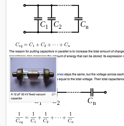
- I don't think it matters, as long as we're consistent and we define the symbol; they're used pretty interchangeably. I think the article's already internally consistent, so we should be OK. Papa November (talk) 02:33, 21 December 2008 (UTC)
- Also, I'm not sure what you mean by a "variable" here. Permittivity is generally a frequency dependent property so it can't be treated as an absolute constant. Papa November (talk) 02:36, 21 December 2008 (UTC)
- Yes, but we don't have anywhere near that depth of treatment here. Neither do any textbooks I suppose I'd recall, (I seem to have lost my main E&M book :v( ) but permittivity does. Meh. Potatoswatter (talk) 06:00, 21 December 2008 (UTC)
- FWIW, looks really fruity on my system (Firefox 3.6.x, Windows Vista x64 SP2). It is very thin and fey, sort of excessively cursive-looking. A Scot might call it "twee". — SMcCandlish Talk⇒ ʕ(Õلō)ˀ Contribs. 06:48, 1 April 2010 (UTC)
Microphony
The main article for microphony as an undesirable effect is microphonics (although it is not a very substantial article). Condenser microphone is certainly the same physical effect but is not really in the context of non-ideal. Do you want that changed? SpinningSpark 12:20, 21 December 2008 (UTC)
- Yes. Have at it. Binksternet (talk) 16:28, 21 December 2008 (UTC)
- Thanks, sorry. Potatoswatter (talk) 04:08, 22 December 2008 (UTC)
Peripheral articles and Category:Capacitors
There's a whole mess of other articles about capacitors. (Guess they're pretty sexy.) I think it would be a good idea to keep our eyes open and make sure they're all in the category. A number of them should be merged into electrolytic capacitor. Potatoswatter (talk) 04:08, 22 December 2008 (UTC)
Uh, "The common parallel plate model reduces such a capacitor to a one-dimensional cross section." I know nothing about capacitors, but wouldn't two broad plates separated by a small distance be commonly modeled in two dimensions? (heck, the picture uses three). If the sentence is truly about a one-dimensional mathematical model, wouldn't it be better placed well before the intro of the concept of parallel plates? —Joel D. Reid (talk) 04:23, 27 December 2008 (UTC)
- Yes, I agree it was a little confusing. I've rewritten it to avoid the discussion of dimensionality as it distracts the reader from the point (simple model, uniform field etc). We need references still. Papa November (talk) 10:28, 27 December 2008 (UTC)
GA review
Would the other editors taking part in this collaboration be agreeable to putting this article up for GA review. I don't have a great deal of experience of this, but when I have been through it before the main things are that [1] you keep monitoring the review as it progresses so that problems are dealt with in a timely manner (otherwise the reviewer loses interest and goes away) and [2] absolutely everything has to be referenced, ie every para. If you are all prepared to work on the article at this level I propose putting it up.
Also, I think the ESR section needs some work, the maths looks gastly. A diagram would help to simplify it. I will work on that bit if there are no objections. SpinningSpark 20:51, 5 January 2009 (UTC)
- No, it needs a lot more refs, and we haven't even touched much of the second half. Sorry I haven't continued to work on it, and I will be moving away and unable to work on next month's collaboration :v( . Yeah, ESR really needs a phasor diagram. Even when rewriting, it's hard for me to accomplish more than incremental improvement. Potatoswatter (talk) 22:21, 5 January 2009 (UTC)
- I agree, we're nowhere near the correct level of referencing yet :( I'm also pretty busy writing my thesis at the minute, so I'm out of action for a while, I'm afraid. I'll get back to the article soon though! Papa November (talk) 22:34, 5 January 2009 (UTC)
Discovered in glass jars?
"Capacitors were discovered in glass jars in 1745 . . ."? How about "The first form of capacitor was the Leyden jar, invented in 1745 . . ." --ChetvornoTALK 15:55, 29 January 2009 (UTC)
- Yeah, that edit isn't my best-ever material… very late night. I'm not sure whether Ewald Georg von Kleist's "Kliestian Jar" differs in some way from the Leyden jar, such as the addition of water inside. The other WP articles strongly imply they're exactly the same thing, but is there a good source for this? Potatoswatter (talk) 19:28, 29 January 2009 (UTC)
- Indeed this is the case… confusing that nobody could repeat Kleist's experiment. Potatoswatter (talk) 19:39, 29 January 2009 (UTC)
Connecting capacitors in a HT line
Friends, i am a HT consumer in india. in our montly billing our power factor is only 0.89. it has been advised by the electricity board people to add capacitors in our circuit. i wish to kno how the rating of the capacitor is arrived at and also how this has to be connected in the circuit.i heard that extra precautions need to be taken while switching on the Generator. i heard while switching on the circuit the capacitor needs to be disconnected.please throw some light on this. —Preceding unsigned comment added by 59.90.213.170 (talk) 13:16, 11 March 2009 (UTC)
- This page is for discussing improvements to the article, not for discussion of the subject itself. You might try Wikipedia:Reference desk/Science though, where the volunteers will try to answer any knowledge question. SpinningSpark 14:14, 11 March 2009 (UTC)
Snap-in capacitors?
In looking through electronic catalogs, I see that certain electrolytic capacitors are referred to as “Snap-In” capacitors, but I do not know what that means. Does it refer to a socket type - or what? An explanation would be appropriate for this article. I am sure that some thought could be give to expand this article to include definitions for many of the jargon words pertaining to capacitors. Stan (talk) 18:00, 13 April 2009 (UTC)
- Snap-in refers to the lead type, which is preformed such that the capacitor holds itself in place when inserted in the pcb prior to soldering. Traditional component leads require to be formed and cut prior to insertion, thus a manufacturing stage is saved. I do not think it is particularly relevant to the article as this feature is not specific to capacitors and can be found on other components. SpinningSpark 22:48, 14 April 2009 (UTC)
Unknown abbreviation
In the last section:
Capacitors used in RF or sustained high-current applications can overheat,
What does RF stand for? A quick google search didn't turn up something useful. Perhaps someone can add it to the article. Thanks Panoramix303 (talk) 22:24, 22 May 2009 (UTC)
Radio frequency. SpinningSpark 23:12, 22 May 2009 (UTC)
- wikilink added--Thorseth (talk) 06:38, 23 May 2009 (UTC)""::
- Thanks Panoramix303 (talk) 11:36, 23 May 2009 (UTC)
Polarised vs. non-polarised capacitors?
wat's difference between polarised and non-polarised capacitors and their functions? —Preceding unsigned comment added by 115.99.0.27 (talk) 08:48, 29 June 2009 (UTC)
- A "polarized capacitor" probably refers to an electrolytic capacitor. As it saya in the 'Dielectric' section, these use a liquid electrolyte. They have much higher capacitance than other types, but have poor tolerances, and high leakage current. They are mainly used in power supplies, to filter (smooth) the DC output voltage. The article omits the most important characteristic, which is that electrolytic capacitors can only have one polarity of voltage applied to them. Their two leads are labelled with a (+) and a (-), and if a reverse voltage is applied, it will destroy them. --ChetvornoTALK 17:30, 29 June 2009 (UTC)
- See electrolytic capacitor. An electrolyte is a conductive liquid solution. The electrolyte forms one terminal and oxidizes the surface of a piece of metal which forms the other terminal. The oxide is the dielectric. If you run current the wrong way, you get electron transfer leading to a redox chemical reaction which dissolves the metal terminal. So, polarized capacitors aren't fundamentally different in any way, they just have some electrochemical sensitivity. Potatoswatter (talk) 21:07, 29 June 2009 (UTC)
- Correct me if I'm wrong, but I was under the impression that the dielectric would be destroyed, rather than a metal terminal, if the wrong polarity of voltage is applied. A similar effect can happen, albeit more slowly, if an electrolytic capacitor has no voltage applied over a period of years. The oxide dielectric will gradually deteriorate, until the capacitor cannot withstand significant voltage and will short out if voltage is suddenly applied. If you turn on an old piece of equipment which has been sitting unused for many years, it may pop and smoke may come out. This is most commonly due to one or more electrolytic capacitors having insufficient dielectric remaining to withstand the suddenly applied voltage. This is a topic which is briefly covered, but perhaps understated, in the Electrolytic capacitor article. Wildbear (talk) 07:21, 30 June 2009 (UTC)
- Everything gets destroyed if the metal is dissolved. The metal, the electrolyte, and the oxide layer. If the electrolyte is full of metal, it won't oxidize anything. Potatoswatter (talk) 19:46, 1 July 2009 (UTC)
- Correct me if I'm wrong, but I was under the impression that the dielectric would be destroyed, rather than a metal terminal, if the wrong polarity of voltage is applied. A similar effect can happen, albeit more slowly, if an electrolytic capacitor has no voltage applied over a period of years. The oxide dielectric will gradually deteriorate, until the capacitor cannot withstand significant voltage and will short out if voltage is suddenly applied. If you turn on an old piece of equipment which has been sitting unused for many years, it may pop and smoke may come out. This is most commonly due to one or more electrolytic capacitors having insufficient dielectric remaining to withstand the suddenly applied voltage. This is a topic which is briefly covered, but perhaps understated, in the Electrolytic capacitor article. Wildbear (talk) 07:21, 30 June 2009 (UTC)
New variable capacitor image
I made a photo of a variable capacitor made of 2 wires near each other in a frame:

At least that's what I think this is supposed to be. Not sure, if another picture of a cap improves these articles, but this one clearly shows the "inside" of a cap. You may add it to the articles Capacitor, Types_of_capacitor and/or Variable_capacitor.
Should I trim the irrelevant stuff from this image?
- There's a lot of irrelevant stuff there, and that's not a common variable cap design. Apparently it's even unfamiliar to you… the one time I took apart a variable cap it had a stack of rotating semicircular plates. Potatoswatter (talk) 06:23, 9 July 2010 (UTC)
For less technical audiences?
I am an educated person, though not in physics. (I took undergrad courses in physics & calculus ~15 years ago, but my PhD is in nutrition.)
I am now training as a volunteer at a large science museum where I live. I will be conducting demonstrations for tour and family groups (mostly kids), including a demonstration on static electricity. Part of the demonstration uses Leyden jars. In my search for more information about how Leyden jars work, I have been frustrated by technical articles describing ratios of charge to potential differences and such when what I really wanted to know was where the electrons went and how the charge was changed on the outer plate in response to the inner plate. Does the outer plate have to be grounded to allow the opposite charge to accumulate? Or is it a partial charge resulting from electron movement within the plate itself? What determines the voltage of an arc caused by touching the pole? Is it a simple matter of how many electrons are stored in one plate or the other? (I'm not looking for these answers on this talk page, just listing the kinds of questions I wanted to learn about in the article but had difficulty with. No need to respond directly to these questions here on the talk page.)
I just want you knowledgeable and talented physics and math people to know that this one guy (me) had a really difficult time learning what I wanted to know from this page, and I want to ask you all to consider presenting information here in a manner that might be more understandable to people like me who aren't that strong on our physics or calculus. I think a kid working on a transistor radio in shop class should be able to take away at least basic knowledge of how capacitors function. I appreciate the fact that all of this technical information is here for anyone who wants to learn the details, but please consider writing a basic description of the principles with us laypeople in mind -- maybe in its own section.
But please don't think of this as a harsh criticism. I truly do appreciate the work you've all done to bring an enormous amount of information to the Wikipedia knowledge base! Someday I might want to brush up on my physics & learn this stuff properly. Dcs002 (talk) 01:01, 10 October 2009 (UTC)
- This sort of specific constructive criticism is what all the electrotechnology article need and don't get. They get written by hobbyists, who have incomplete and eccentric notions of the subject and generally treat it in the most superficial fashion. Rarely an article gets visited by someone knowledgeable, who gets scared off when he gets overwritten by some teenager with time on his hands. Or, worse yet, some curmudgeon overturns an article based on his vast experience and knowledge, except that he can't write three consecutive clear sentences without diving into jargon. People who can write *well* get paid for doing it, and don't come here. There's an upper limit to the quality level of any Wikipedia electrotechnology article that is very low indeed. Though I'm sure the articles on history, geography, mathematics, chemistry, etc. are in much better condition.... (from what I've read, the basics are, anyway.) Editing a Wikipedia article is a very good way to discover your own ignorance, as I have found. --Wtshymanski (talk) 01:30, 10 October 2009 (UTC)