
IEEE 802.1aq
This article contains content that is written like an advertisement. (May 2023) |
| Internet protocol suite |
|---|
| Application layer |
| Transport layer |
| Internet layer |
| Link layer |
IEEE 802.1aq is an amendment to the IEEE 802.1Q networking standard which adds support for Shortest Path Bridging (SPB). This technology is intended to simplify the creation and configuration of Ethernet networks while enabling multipath routing.[1][2][3]
SPB is designed to replace the older spanning tree protocols: IEEE 802.1D STP, IEEE 802.1w RSTP, and IEEE 802.1s MSTP. These block any redundant paths that can result in a switching loop, whereas SPB allows all paths to be active with multiple equal-cost paths, provides much larger layer-2 topologies,[4] supports faster convergence times, and improves the efficiency by allowing traffic to load share across all paths of a mesh network.[5][6][7][8] It is designed to preserve the plug-and-play nature that established Ethernet as the de facto protocol at layer 2.
The technology provides VLANs on native Ethernet infrastructures using a link-state protocol to advertise both topology and VLAN membership. Packets are encapsulated at the edge either in MAC-in-MAC per IEEE 802.1ah or tagged per IEEE 802.1Q or IEEE 802.1ad and transported only to other members of VLAN. Unicast, multicast, and broadcast are supported and all routing is on symmetric shortest paths.
The control plane is based on the Intermediate System to Intermediate System (IS-IS) routing protocol, leveraging a small number of extensions defined in RFC 6329.[9]
History
[edit]On 4 March 2006 the working group posted 802.1aq draft 0.1.[10] In March 2012 the IEEE approved the 802.1aq standard.[11]
In May 2013, the first public multivendor interoperability was demonstrated as SPB served as the backbone for Interop 2013 in Las Vegas.[12] In 2013 and 2014 SPB was used to build the InteropNet backbone with only one-tenth the resources of prior years.[13] During Interop 2014 SPB was used as the backbone protocol which can enable software-defined networking (SDN) functionalities.[14][15]
The 2014 Winter Olympics were the first "fabric-enabled" Games using SPB "IEEE 802.1aq" technology.[16][17] During the games this fabric network could handle up to 54 Tbit/s of traffic.[18]
Associated protocols
[edit]- IEEE 802.1Q-2014 - Bridges and Bridged Networks - This standard incorporates Shortest Path Bridging (IEEE 802.1aq) with the following: IEEE Std 802.1Q-2011, IEEE Std 802.1Qbe-2011, IEEE Std 802.1Qbc-2011, IEEE Std 802.1Qbb-2011, IEEE Std 802.1Qaz-2011, IEEE Std 802.1Qbf-2011, IEEE Std 802.1Qbg-2012, IEEE Std 802.1Q-2011/Cor 2–2012, and IEEE Std 802.1Qbp-2014, and much functionality previously specified in 802.1D.[19]
- IEEE 802.1ag - Connectivity Fault Management (CFM)
- IEEE 802.1Qbp - Equal Cost Multiple Paths in Shortest Path Bridging[20]
- IEEE P802.1Qcj - Automatic Attachment to Provider Backbone Bridging (PBB) services[21]
- RFC 6329 - IS-IS Extensions Supporting IEEE 802.1aq Shortest Path Bridging
RFC 6329
[edit]The Intermediate System to Intermediate System (IS-IS) protocol, as defined in the IETF proposed standard RFC 6329, is used as the control plane for SPB.[22][23][24][25] SPB requires no state machine or other substantive changes to IS-IS, and simply requires a new Network Layer Protocol Identifier (NLPID) and set of TLVs.[9]: Section 13
SPB allows for shortest-path forwarding in a mesh-connected Ethernet network utilizing multiple equal-cost paths. This permits SPB to support large Layer 2 topologies, with faster convergence, and improved use of the mesh topology when compared to networks configured with Spanning Tree Protocol. SPB augments IS-IS with a small number of TLVs and sub-TLVs, and supports two Ethernet encapsulating data paths, 802.1ad Provider Bridges (PB) and 802.1ah Provider Backbone Bridges (PBB).
SPB is designed to run in parallel with other network-layer protocols such as IPv4 and IPv6. Standards mandate that the failure of two nodes to establish an SPB adjacency will not have a collateral impact, such as the rejection of an adjacency for other network-layer protocols (e.g. OSPF).
Protocol extensions
[edit]The IS-IS extensions defined in RFC 6329 that deliver standardized support for 802.1aq SPB are:
- IS-IS Hello (IIH) Protocol Extensions
- Node Information Extensions
- Adjacency Information Extensions
- Service Information Extensions
IS-IS Hello (IIH) protocol extensions
[edit]802.1aq has been designed to operate in parallel with other network layer protocols such as IPv4 and IPv6; therefore, failure of two nodes to establish an SPB adjacency will not cause network layer protocols to also reject an adjacency. RFC 6328 assigns 802.1aq the Network Layer Protocol ID (NLPID) value 0xC1.[26] This NLPID is used by SPB Bridges to indicate their ability to form adjacencies and operate as part of an 802.1aq domain. 802.1aq frames flow on adjacencies that advertise this NLPID in both directions, and nodes regard an adjacency that has not been advertised in both directions as non-existent (with infinite link metric). 802.1aq augments the normal IIH PDU with three new TLVs, which like all other SPB TLVs, travel within Multi-Topology TLVs, therefore allowing multiple logical instances of SPB within a single IS-IS protocol instance.
SPB can use many VIDs, agreeing on which VIDs are used for which purposes. The IIH PDUs carry a digest of all the used VIDs, referred to as the Multiple Spanning Tree Configuration TLV which uses a common and compact encoding reused from 802.1Q.
For the purposes of loop prevention SPB neighbors may also support a mechanism to verify that the contents of their topology databases are synchronized. Exchanging digests of SPB topology information, using the optional SPB-Digest sub-TLV, allows nodes to compare information and take specific action where a mismatch in topology is indicated.
Finally, SPB needs to know which shortest path tree (SPT) sets are being used by which VIDs, and this is carried in the Base VLAN Identifiers TLV.
Node information extensions
[edit]All SPB nodal information extensions travel within a new Multi-Topology (MT) capability TLV. There can be one or many MT-Capability TLVs present, depending on the amount of information that needs to be carried.
The SPB Instance sub-TLV gives the Shortest Path Source ID (SPSourceID) for this node or topology instance. This is used in the formation of multicast destination addresses (DAs) for frames originating from this node or instance.
There are multiple ECT algorithms defined for SPB and additional algorithms may be defined in the future including but not limited to ECMP- or hash-based behaviors and (*,G) Multicast trees. These algorithms will use this optional TLV to define new algorithm parametric data. For tie-breaking parameters, there are two broad classes of algorithms, one that uses nodal data to break ties and one that uses link data to break ties. The SPB Instance Opaque Equal cost Tree Algorithm TLV is used to associate opaque tie-breaking data with a node.
Adjacency information extensions
[edit]The SPB Link Metric sub-TLV occurs within the Multi-Topology Intermediate System Neighbor TLV or within the Extended IS Reachability TLV. SPB Adjacency Opaque Equal Cost Tree Algorithm TLV also occurs within the Multi-Topology Intermediate System TLV or the Extended IS Reachability TLV. Where this sub-TLV is not present for an IS-IS adjacency, that adjacency will not carry SPB traffic for the given topology instance.
Service information extensions
[edit]The SPBM Service Identifier and Unicast Address TLV is used to introduce service group membership on the originating node or to advertise an additional B-MAC unicast address present on, or reachable by the node. The SPBV MAC Address TLV is the IS-IS sub-TLV used for advertisement of group MAC addresses in SPBV mode.
Benefits
[edit]Shortest Path Bridging-VID (SPBV) and Shortest Path Bridging-MAC (SPBM) are two operating modes of 802.1aq. Both inherit key benefits of link state routing:
- the ability to use all available physical connectivity, because loop avoidance uses a control plane with a global view of network topology
- fast restoration of connectivity after failure, again because of link state routing's global view of network topology
- under failure, the property that only directly affected traffic is impacted during restoration
- rapid restoration of broadcast and multicast connectivity, because IS-IS floods all of the required information in the SPB extensions to IS-IS, thereby allowing unicast and multicast connectivity to be installed in parallel, with no need for a second phase signaling process to run over the converged unicast topology to compute and install multicast trees.
SPBM offers emulation of a transparent Ethernet LAN segment. It implements VLANs with scoped multicast trees, which means no egress discard of broadcast, unknown-unicast and multicast traffic, a feature common to approaches that use a small number of shared trees, hence the network does not simply degrade with size as the percentage of frames discarded goes up.
The carrier-space equivalent of this application is the delivery of Ethernet VPN services to Enterprises over common carrier infrastructure. The required attributes are fundamentally the same; complete transparency for customer Ethernet services (both point-to-point and LAN), and complete isolation between one customer's traffic and that of all other customers.
A further consequence of SPBM's transparency in both data plane and control plane is that it delivers the MEF 6.1 service set. It also provides the carrier with the toolkit to support geo-redundant broadband backhaul; in these applications, many DSLAMs or other access equipment must be backhauled to multiple Broadband Remote Access Server (BRAS) sites, with application-determined binding of sessions to a BRAS. However, DSLAMs must not be allowed to communicate with each other, because carriers then lose the ability to control peer-to-peer connectivity. MEF E-TREE does just this, and further provides an efficient multicast fabric for the distribution of IPTV.
SPBM offers both an ideal multicast replication model, where packets are replicated only at fork points in the shortest path tree that connects members, and also the less state-intensive head-end replication model where in essence serial unicast packets are sent to all other members along the same shortest path first tree. These two models are selected by specifying properties of the service at the edge which affect the transit node decisions on multicast state installation. This allows for a trade-off to be made between optimum transit replication points (with their larger state costs) vs. reduced core state (but much more traffic) of the head-end replication model. These selections can be different for different members of the same Individual Service ID (I-SID) allowing different trade-offs to be made for different members.
Figure 5 below is a quick way to understand what SPBM is doing on the scale of the entire network. Figure 5 shows how a 7-member E-LAN is created from the edge membership information and the deterministic distributed calculation of per source, per service trees with transit replication. Head-end replication is not shown as it is trivial and simply uses the existing unicast FIBs to forward copies serially to the known other receivers.
Operations and management
[edit]802.1aq builds on all existing Ethernet operations, administration and management (OA&M). Since 802.1aq ensures that its unicast and multicast packets for a given virtual LAN (VLAN) follow the same forward and reverse path and use completely standard 802 encapsulations, all the methods of 802.1ag and Y.1731[27] operate unchanged on an 802.1aq network.
High level
[edit]802.1aq is the IEEE-sanctioned link state Ethernet control plane for all IEEE VLANs covered in IEEE 802.1Q.[28] The Shortest Path Bridging virtual local area network identifier (VLAN ID) or Shortest Path Bridging VID (SPBV) provides a capability that is backward compatible with spanning tree technologies. The SPBM provides additional values that use Provider Backbone Bridge (PBB) capabilities. SPB (the generic term for both) combines an Ethernet data path (either IEEE 802.1Q in the case of SPBV, or Provider Backbone Bridges (PBBs) IEEE 802.1ah in the case of SPBM) with an IS-IS link state control protocol running between Shortest Path bridges (Network-to-network interface (NNI) links). The link state protocol is used to discover and advertise the network topology and compute SPTs from all bridges in the SPT Region.
In SPBM, the backbone MAC (B-MAC) addresses of the participating nodes and also the service membership information for interfaces to non-participating devices (User–network interface (UNI) ports) is distributed. Topology data is then input to a calculation engine which computes symmetric shortest path trees based on minimum cost from each participating node to all other participating nodes. In SPBV these trees provide a shortest path tree where individual MAC address can be learned and group address membership can be distributed. In SPBM the shortest path trees are then used to populate forwarding tables for each participating node's individual B-MAC addresses and for group addresses; Group multicast trees are subtrees of the default shortest path tree formed by (source, group) pairing. Depending on the topology, several different equal-cost multi-path trees are possible and SPB supports multiple algorithms per IS-IS instance.
In SPB as with other link-state-based protocols, the computations are done in a distributed fashion. Each node computes the Ethernet-compliant forwarding behavior independently based on a normally synchronized common view of the network and UNI ports. Ethernet filtering Database (or forwarding) tables are populated locally to independently and deterministically implement its portion of the network forwarding behavior.
The two different flavors of data path give rise to two slightly different versions of this protocol. One (SPBM) is intended where complete isolation of many separate instances of client LANs and their associated device MAC addresses is desired, and it therefore uses a full encapsulation (MAC-in-MAC a.k.a. IEEE 802.1ah). The other (SPBV) is intended where such isolation of client device MAC addresses is not necessary, and it reuses only the existing VLAN tag on participating NNI links. Chronologically SPBV came first, with the project originally being conceived to address scalability and convergence of MSTP.
At the time the specification of Provider Backbone bridging was progressing and it became apparent that leveraging both the PBB data plane and a link state control plane would significantly extend Ethernet's capabilities and applications. Provider Link State Bridging (PLSB) was a straw man proposal brought to the IEEE 802.1aq Shortest Path Bridging Working Group, in order to provide a concrete example of such a system. As IEEE 802.1aq standardization has progressed, some of the detailed mechanisms proposed by PLSB have been replaced by functional equivalents, but all of the key concepts embodied in PLSB are being carried forward into the standard.
The two flavors (SPBV and SPBM) will be described separately although the differences are almost entirely in the data plane.
Shortest Path Bridging-VID
[edit]Shortest Path bridging enables shortest path trees for VLAN Bridges all IEEE 802.1 data planes and SPB is the term used in general. Recently there has been a lot of focus on SPBM as explained due to its ability to control the new PBB data plane and leverage certain capabilities such as removing the need to do B-MAC learning and automatically creating individual (unicast) and group (multicast) Trees. SPBV was actually the original project that endeavored to enable Ethernet VLANs to better utilize mesh networks.
A primary feature of Shortest Path bridging is the ability to use Link State IS-IS to learn network topology. In SPBV the mechanism used to identify the tree is to use a different Shortest Path VLAN ID (VID) for each source bridge. The IS-IS topology is leveraged both to allocate unique SPVIDs and to enable shortest path forwarding for individual and group addresses. Originally targeted for small low configuration networks SPB grew into a larger project encompassing the latest provider control plane for SPBV and harmonizing the concepts of Ethernet data plane. Proponents of SPB believe that Ethernet can leverage link state and maintain the attributes that have made Ethernet one of the most encompassing data plane transport technologies. When we refer to Ethernet it is the layer 2 frame format defined by IEEE 802.3 and IEEE 802.1. Ethernet VLAN bridging IEEE 802.1Q is the frame forwarding paradigm that fully supports higher level protocols such as IP.
SPB defines a shortest path Region which is the boundary of the shortest path topology and the rest of the VLAN topology (which may be any number of legacy bridges.) SPB operates by learning the SPB capable bridges and growing the Region to include the SPB capable bridges that have the same Base VID and MSTID configuration digest (Allocation of VIDs for SPB purposes).
SPBV builds shortest path trees that support Loop Prevention and optionally support loop mitigation on the SPVID. SPBV still allows learning of Ethernet MAC addresses but it can distribute multicast address that can be used to prune the shortest path trees according to the multicast membership either through Multiple MAC Registration Protocol (MMRP) or directly using IS-IS distribution of multicast membership.
SPBV builds shortest path trees but also interworks with legacy bridges running Rapid Spanning Tree Protocol and Multiple Spanning Tree Protocol. SPBV uses techniques from MSTP Regions to interwork with non-SPT regions behaving logically as a large distributed bridge as viewed from outside the region.
SPBV supports shortest path trees but SPBV also builds a spanning tree which is computed from the link state database and uses the Base VID. This means that SPBV can use this traditional spanning tree for computation of the Common and Internal Spanning Tree (CIST). The CIST is the default tree used to interwork with other legacy bridges. It also serves as a fallback spanning tree if there are configuration problems with SPBV.
SPBV has been designed to manage a moderate number of bridges. SPBV differs from SPBM in that MAC addresses are learned on all bridges that lie on the shortest path and a shared VLAN learning is used since destination MACs may be associated with multiple SPVIDs. SPBV learns all MACs it forwards even outside the SPBV region.
Shortest Path Bridging-MAC
[edit]SPBM reuses the PBB data plane which does not require that the Backbone Core Bridges (BCB) learn encapsulated client addresses. At the edge of the network the C-MAC (client) addresses are learned. SPBM is very similar to PLSB (Provider Link State Bridging) using the same data and control planes but the format and contents of the control messages in PLSB are not compatible.
Individual MAC frames (unicast traffic) from an Ethernet attached device that are received at the SPBM edge are encapsulated in a PBB (mac-in-mac) IEEE 802.1ah header and then traverse the IEEE 802.1aq network unchanged until they are stripped of the encapsulation as they egress back to the non-participating attached network at the far side of the participating network.
Ethernet destination addresses (from UNI port attached devices) perform learning over the logical LAN and are forwarded to the appropriate participating B-MAC address to reach the far end Ethernet destination. In this manner Ethernet MAC addresses are never looked up in the core of an IEEE 802.1aq network. When comparing SPBM to PBB, the behavior is almost identical to a PBB IEEE 802.1ah network. PBB does not specify how B-MAC addresses are learned and PBB may use a spanning tree to control the B-VLAN. In SPBM the main difference is that B-MAC address are distributed or computed in the control plane, eliminating the B-MAC learning in PBB. Also SPBM ensures that the route followed is shortest path tree.
The forward and reverse paths used for unicast and multicast traffic in an IEEE 802.1aq network are symmetric. This symmetry permits the normal Ethernet Continuity Fault Messages (CFM) IEEE 802.1ag to operate unchanged for SPBV and SPBM and has desirable properties with respect to time distribution protocols such as Precision Time Protocol (PTP Version 2). Also existing Ethernet loop prevention is augmented by loop mitigation to provide fast data plane convergence.
Group address and unknown destination individual frames are optimally transmitted to only members of the same Ethernet service. IEEE 802.1aq supports the creation of thousands of logical Ethernet services in the form of E-LINE, E-LAN or E-TREE constructs which are formed between non-participating logical ports of the IEEE 802.1aq network. These group address packets are encapsulated with a PBB header which indicates the source participating address in the SA while the DA indicates the locally significant group address this frame should be forwarded on and which source bridge originated the frame. The IEEE 802.1aq multicast forwarding tables are created based on computations such that every bridge which is on the shortest path between a pair of bridges which are members of the same service group will create proper forwarding database (FDB) state to forward or replicate frames it receives to that members of that service group. Since the group address computation produce shortest path trees, there is only ever one copy of a multicast packet on any given link. Since only bridges on a shortest path between participating logical ports create forwarding database (FDB) state the multicast makes the efficient use of network resources.
The actual group address forwarding operation operates more or less identically to classical Ethernet, the backbone destination address (B-DA)+ backbone VLAN identifier (B-VID) combination are looked up to find the egress set of next hops. The only difference compared with classical Ethernet is that reverse learning is disabled for participating bridge backbone media access control (B-MAC) addresses and is replaced with an ingress check and discard (when the frame arrives on an incoming interface from an unexpected source). Learning is however implemented at the edges of the SPBM multicast tree to learn the B-MAC to MAC address relationship for correct individual frame encapsulation in the reverse direction (as packets arrive over the Interface).
Properly implemented an IEEE 802.1aq network can support up to 1000 participating bridges and provide tens of thousands of layer 2 E-LAN services to Ethernet devices. This can be done by simply configuring the ports facing the Ethernet devices to indicate they are members of a given service. As new members come and go, the IS-IS protocol will advertise the I-SID membership changes and the computations will grow or shrink the trees in the participating node network as necessary to maintain the efficient multicast property for that service.
IEEE 802.1aq has the property that only the point of attachment of a service needs configuration when a new attachment point comes or goes. The trees produced by the computations will automatically be extended or pruned as necessary to maintain connectivity. In some existing implementations this property is used to automatically (as opposed to through configuration) add or remove attachment points for dual-homed technologies such as rings to maintain optimum packet flow between a nonparticipating ring protocol and the IEEE 802.1aq network by activating a secondary attachment point and deactivating a primary attachment point.
Failure recovery
[edit]Failure recovery is as per normal IS-IS with the link failure being advertised and new computations being performed, resulting in new FDB tables. Since no Ethernet addresses are advertised or known by this protocol, there is no re-learning required by the SPBM core and its learned encapsulations are unaffected by a transit node or link failure.
Fast link failure detection may be performed using IEEE 802.1ag Continuity Check Messages (CCMs) which test link status and report a failure to the IS-IS protocol. This allows much faster failure detection than is possible using the IS-IS hello message loss mechanisms.
Both SPBV and SPBM inherit the rapid convergence of a link state control plane. A special attribute of SPBM is its ability to rebuild multicast trees in a similar time to unicast convergence, because it substitutes computation for signaling. When an SPBM bridge has performed the computations on a topology database, it knows whether it is on the shortest path between a root and one or more leaves of the SPT and can install state accordingly. Convergence is not gated by incremental discovery of a bridge's place on a multicast tree by the use of separate signaling transactions. However, SPBM on a node does not operate completely independently of its peers, and enforces agreement on the current network topology with its peers. This very efficient mechanism uses exchange of a single digest of link state covering the entire network view, and does not need agreement on each path to each root individually. The result is that the volume of messaging exchanged to converge the network is in proportion to the incremental change in topology and not the number of multicast trees in the network. A simple link event that may change many trees is communicated by signaling the link event only; the consequent tree construction is performed by local computation at each node. The addition of a single service access point to a service instance involves only the announcement of the I-SID, regardless of the number of trees. Similarly the removal of a bridge, which might involve the rebuilding of hundreds to thousands of trees, is signaled only with a few link state updates.
Commercial offerings will likely offer SPB over multi-chassis lag. In this environment multiple switch chassis appear as a single switch to the SPB control plane, and multiple links between pairs of chassis appear as an aggregate link. In this context a single link or node failure is not seen by the control plane and is handled locally resulting in sub 50ms recovery times.
Animations
[edit]Following are three animated GIFs which help to show the behavior of 802.1aq.
The first of these gifs, shown in Figure 5, demonstrates the routing in a 66 node network where we have created a 7-member E-LAN using ISID 100. In this example we show the equal cost tree (ECT) created from each member to reach all of the other members. We cycle through each member to show the full set of trees created for this service. We pause at one point to show the symmetry of routing between two of the nodes and emphasize it with a red line. In each case the source of the tree is highlighted with a small purple V.
The second of these animated gifs, shown in Figure 6, demonstrates 8 ECT paths in the same 66 node network as Figure 4. In each subsequent animated frame the same source is used (in purple) but a different destination is shown (in yellow). For each frame, all of the shortest paths are shown superimposed between the source and destination. When two shortest paths traverse the same hop, the thickness of the lines being drawn is increased. In addition to the 66 node network, a small multi level Data Center style network is also shown with sources and destinations both within the servers (at the bottom) and from servers to the router layer at the top. This animation helps to show the diversity of the ECT being produced.
The last of these animated gifs, shown in Figure 7, demonstrates source destination ECT paths using all 16 of the standard algorithms currently defined.
-
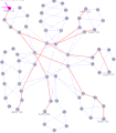 Figure 5 - Animated E-LAN example in a 66 node 802.1aq network with 7 members
 -
 Figure 6 - Animated ECT example in a 66 node 802.1aq network with 8 ECT
 -
 Figure 7 - Animated ECT example 36 node 802.1aq network with 16 ECT
.gif)
.gif)
.gif)
Details
[edit]Equal cost multi tree
[edit]Sixteen equal cost multi tree (ECMT) paths are initially defined, however there are many more possible. ECMT in an IEEE 802.1aq network is more predictable than with internet protocol (IP) or multiprotocol label switching (MPLS) because of symmetry between the forward and reverse paths. The choice as to which ECMT path will be used is therefore an operator assigned head end decision while it is a local / hashing decision with IP/MPLS.
IEEE 802.1aq, when faced with a choice between two equal link cost paths, uses the following logic for its first ECMT tie breaking algorithm: first, if one path is shorter than the other in terms of hops, the shorter path is chosen, otherwise, the path with the minimum Bridge Identifier { BridgePriority concatenated with (IS-IS SysID) } is chosen. Other ECMT algorithms are created by simply using known permutations of the BridgePriority||SysIds. For example, the second defined ECMT algorithm uses the path with the minimum of the inverse of the BridgeIdentifier and can be thought of as taking the path with the maximum node identifier. For SPBM, each permutation is instantiated as a distinct B-VID. The upper limit of multipath permutations is gated by the number of B-VIDs delegated to 802.1aq operation, a maximum of 4094, although the number of useful path permutations would only require a fraction of the available B-VID space. Fourteen additional ECMT algorithms are defined with different bit masks applied to the BridgeIdentifiers. Since the BridgeIdentifier includes a priority field, it is possible to adjust the ECMT behavior by changing the BridgePriority up or down.
A service is assigned to a given ECMT B-VID at the edge of the network by configuration. As a result, non-participating packets associated with that service are encapsulated with the VID associated with the desired ECMT end to end path. All individual and group address traffic associated with this service will therefore use the proper ECMT B-VID and be carried symmetrically end to end on the proper equal cost multi path. Essentially the operator decides which services go in which ECMT paths, unlike a hashing solution used in other systems such as IP/MPLS. Trees can support link aggregation (LAG) groups within a tree "branch" segment where some form of hashing occurs.
This symmetric and end-to-end ECMT behavior gives IEEE 802.1aq a highly predictable behavior and offline engineering tools can accurately model exact data flows. The behavior is also advantageous to networks where one-way delay measurements are important. This is because the one way delay can be accurately computed as 1/2 the round-trip delay. Such computations are used by time distribution protocols such as IEEE 1588 for frequency and time-of-day synchronization as required between precision clock sources and wireless base stations.
Shown above are three figures [5,6,7] which show 8 and 16 equal cost tree (ECT) behavior in different network topologies. These are composites of screen captures of an 802.1aq network emulator and show the source in purple, the destination in yellow, and then all the computed and available shortest paths in pink. The thicker the line, the more shortest paths use that link. The animations show three different networks and a variety of source and destination pairs which continually change to help visualize what is happening.
The equal cost tree (ECT) algorithms can be almost extended through the use of OPAQUE data which allows extensions beyond the base 16 algorithms more or less infinitely. It is expected that other standards groups or vendors will produce variations on the currently defined algorithms with behaviors suited for different networks styles. It is expected that numerous shared tree models will also be defined, as will hop by hop hash based equal-cost multi-path (ECMP) style behaviors .. all defined by a VID and an algorithm that every node agrees to run.
Traffic engineering
[edit]802.1aq does not spread traffic on a hop-by-hop basis. Instead, 802.1aq allows assignment of a Service ID (ISID) to a VLAN ID (VID) at the edge of the network. A VID will correspond to exactly one of the possible sets of shortest path nodes in the network and will never stray from that routing. If there are 10 or so shortest paths between different nodes, it is possible to assign different services to different paths and to know that the traffic for a given service will follow exactly the given path. In this manner traffic can easily be assigned to the desired shortest path. In the event that one of the paths becomes overloaded it is possible to move some services off that shortest path by reassigning those service's ISID to a different, less loaded, VID at the edges of the network.
The deterministic nature of the routing makes offline prediction/computation/experimentation of the network loading much simpler since actual routes are not dependent on the contents of the packet headers except for the VLAN identifier.

Figure 4 shows four different equal-cost paths between nodes 7 and 5. An operator can achieve a relatively good balance of traffic across the cut between nodes [0 and 2] and [1 and 3] by assigning the services at nodes 7 and 5 to one of the four desired VIDs. Using more than 4 equal cost tree (ECT) paths in the network will likely allow all 4 of these paths to be used. Balance can also be achieved between nodes 6 and 4 in a similar manner.
In the event that an operator does not wish to manually assign services to shortest paths it is a simple matter for a switch vendor to allow a simple hash of the ISID to one of the available VIDS to give a degree of non-engineered spreading. For example, the ISID modulo the number of ECT-VIDs could be used to decide on the actual relative VID to use.
In the event that the ECT paths are not sufficiently diverse the operator has the option of adjusting the inputs to the distributed ECT algorithms to apply attraction or repulsion from a given node by adjusting that node's Bridge Priority. This can be experimented with via offline tools until the desired routes are achieved at which point the bias can be applied to the real network and then ISIDs can be moved to the resulting routes.
Looking at the animations in Figure 6 shows the diversity available for traffic engineering in a 66 node network. In this animation, there are 8 ECT paths available from each highlighted source to destination and therefore services could be assigned to 8 different pools based on the VID. One such initial assignment in Figure 6 could therefore be (ISID modulo 8) with subsequent fine tuning as required.
Example
[edit]
We will work through SPBM behavior on a small example, with emphasis on the shortest-path trees for unicast and multicast.
The network shown in Figure 1 consists of 8 participating nodes numbered 0 through 7. These would be switches or routers running the IEEE 802.1aq protocol. Each of the 8 participating nodes has a number of adjacencies numbered 1..5. These would likely correspond to interface indexes, or possibly port numbers. Since 802.1aq does not support parallel interfaces each interface corresponds to an adjacency. The port / interface index numbers are of course local and are shown because the output of the computations produce an interface index (in the case of unicast) or a set of interface indexes (in the case of multicast) which are part of the forwarding information base (FIB) together with a destination MAC address and backbone VID.
The network has a fully meshed inner core of four nodes (0..3) and then four outer nodes (4,5,6 and 7), each dual-homed onto a pair of inner core nodes.
Normally when nodes come from the factory they have a MAC address assigned which becomes a node identifier but for the purpose of this example we will assume that the nodes have MAC addresses of the form 00:00:00:00:N:00 where N is the node id (0..7) from Figure 1. Therefore, node 2 has a MAC address of 00:00:00:00:02:00. Node 2 is connected to node 7 (00:00:00:00:07:00) via node 2's interface/5.
The IS-IS protocol runs on all the links shown since they are between participating nodes. The IS-IS hello protocol has a few additions for 802.1aq including information about backbone VIDs to be used by the protocol. We will assume that the operator has chosen to use backbone VIDs 101 and 102 for this instance of 802.1aq on this network.
The node will use their MAC addresses as the IS-IS SysId and join a single IS-IS level and exchange link-state packets (LSPs in IS-IS terminology). The LSPs will contain node information and link information such that every node will learn the full topology of the network. Since we have not specified any link weights in this example, the IS-IS protocol will pick a default link metric for all links, therefore all routing will be minimum hop count.
After topology discovery the next step is distributed calculation of the unicast routes for both ECMP VIDs and population of the unicast forwarding tables (FIBs).

Consider the route from Node 7 to Node 5: there are a number of equal-cost paths. 802.1aq specifies how to choose two of them: the first is referred to as the Low PATH ID path. This is the path which has the minimum node id on it. In this case the Low PATH ID path is the 7->0->1->5 path (as shown in red in Figure 2). Therefore, each node on that path will create a forwarding entry toward the MAC address of node five using the first ECMP VID 101. Conversely, 802.1aq specifies a second ECMP tie-breaking algorithm called High PATH ID. This is the path with the maximum node identifier on it and in the example is the 7->2->3->5 path (shown in blue in Figure 2).
Node 7 will therefore have a FIB that among other things indicates:
- MAC 00:00:00:05:00 / vid 101 the next hop is interface/1.
- MAC 00:00:00:05:00 / vid 102 the next hop is interface/2.
Node 5 will have exactly the inverse in its FIB:
- MAC 00:00:00:07:00 / vid 101 the next hop is interface/1.
- MAC 00:00:00:07:00 / vid 102 the next hop is interface/2.
The intermediate nodes will also produce consistent results so for example node 1 will have the following entries.
- MAC 00:00:00:07:00 / vid 101 the next hop is interface/5.
- MAC 00:00:00:07:00 / vid 102 the next hop is interface/4.
- MAC 00:00:00:05:00 / vid 101 the next hop is interface/2.
- MAC 00:00:00:05:00 / vid 102 the next hop is interface/2.
And Node 2 will have entries as follows:
- MAC 00:00:00:05:00 / vid 101 the next hop is interface/2.
- MAC 00:00:00:05:00 / vid 102 the next hop is interface/3.
- MAC 00:00:00:07:00 / vid 101 the next hop is interface/5.
- MAC 00:00:00:07:00 / vid 102 the next hop is interface/5.
If we had an attached non-participating device at Node 7 talking to a non-participating device at Node 5 (for example Device A talks to Device C in Figure 3), they would communicate over one of these shortest paths with a MAC-in-MAC encapsulated frame. The MAC header on any of the NNI links would show an outer source address of 00:00:00:70:00, an outer destination address of 00:00:00:50:00 and a BVID of either 101 or 102 depending on which has been chosen for this set of non-participating ports/vids. The header once inserted at node 7 when received from node A, would not change on any of the links until it egressed back to non-participating Device C at Node 5. All participating devices would do a simple DA+VID lookup to determine the outgoing interface, and would also check that incoming interface is the proper next hop for the packet's SA+VID. The addresses of the participating nodes 00:00:00:00:00:00 ... 00:00:00:07:00 are never learned but are advertised by IS-IS as the node's SysId.
Unicast forwarding to a non-participating client (e.g. A, B, C, D from Figure 3) address is of course only possible when the first hop participating node (e.g. 7) is able to know which last hop participating node (e.g. 5) is attached to the desired non-participating node (e.g. C). Since this information is not advertised by IEEE 802.1aq it has to be learned. The mechanism for learning is identical to IEEE 802.1ah, in short, the corresponding outer MAC unicast DA, if not known is replaced by a multicast DA and when a response is received, the SA of that response now tells us the DA to use to reach the non-participating node that sourced the response. e.g. node 7 learns that C is reached by node 5.

Since we wish to group/scope sets of non-participating ports into services and prevent them from multicasting to each other, IEEE 802.1aq provides mechanism for per source, per service multicast forwarding and defines a special multicast destination address format to provide this. Since the multicast address must uniquely identify the tree, and because there is a tree per source per unique service, the multicast address contains two components, a service component in the low order 24 bits and a network-wide unique identifier in the upper 22 bits. Since this is a multicast address the multicast bit is set, and since we are not using the standard OUI space for these manufactured addresses, the Local 'L' bit is set to disambiguate these addresses. In Figure 3 above, this is represented with the DA=[7,O] where the 7 represents packets originating from node 7 and the colored O represents the E-LAN service we are scoped within.
Prior to creating multicast forwarding for a service, nodes with ports that face that service must be told they are members. For example, nodes 7,4,5 and 6 are told they are members of the given service, for example service 200, and further that they should be using BVID 101. This is advertised by ISIS and all nodes then do the SPBM computation to determine if they are participating either as a head end or tail end, or a tandem point between other head and tail ends in the service. Since node 0 is a tandem between nodes 7 and 5 it creates a forwarding entry for packets from node 7 on this service, to node 5. Likewise, since it is a tandem between nodes 7 and 4 it creates forwarding state from node 7 for packets in this service to node 4 this results in a true multicast entry where the DA/VID have outputs on two interfaces 1 and 2. Node 2 on the other hand is only on one shortest path in this service and only creates a single forwarding entry from node 7 to node 6 for packets in this service.
Figure 3 only shows a single E-LAN service and only the tree from one of the members, however very large numbers of E-LAN services with membership from 2 to every node in the network can be supported by advertising the membership, computing the tandem behaviors, manufacturing the known multicast addresses and populating the FIBs. The only real limiting factors are the FIB table sizes and computational power of the individual devices both of which are growing yearly in leaps and bounds.
Implementation notes
[edit]This section needs additional citations for verification. (June 2024) |
802.1aq takes IS-IS topology information augmented with service attachment (I-SID) information, does a series of computations and produces a forwarding table (filtering table) for unicast and multicast entries.
The IS-IS extensions that carry the information required by 802.1aq are given in the isis-layer2 IETF document listed below.
An implementation of 802.1aq will first modify the IS-IS hellos to include an NLPID (network layer protocol identifier) of 0xC01 in their Protocols-Supported type–length–value (TLV) (type 129) which has been reserved for 802.1aq. The hellos also must include an MSTID (which gives the purpose of each VID) and finally each ECMT behavior must be assigned to a VID and exchanged in the hellos. The hellos would normally run untagged. Note that NLPID of IP is not required to form an adjacency for 802.1aq but also will not prevent an adjacency when present.
The links are assigned 802.1aq specific metrics which travel in their own TLV (Type Length Value) which is more or less identical to the IP link metrics. The calculations will always use the maximum of the two unidirectional link metrics to enforce symmetric route weights.
The node is assigned a mac address to identify it globally and this is used to form the IS-IS SYSID. A box mac would normally serve this purpose. The Area-Id is not directly used by 802.1aq but should, of course, be the same for nodes in the same 802.1aq network. Multiple areas/levels are not yet supported.
The node is further assigned an SPSourceID which is a 20 bit network wide unique identifier. This can often be the low 20 bits of the SYSID (if unique) or can be dynamically negotiated or manually configured.
The SPSourceID and the ECMT assignments to B-VIDs are then advertised into the IS-IS network in their own 802.1aq TLV.
The 802.1aq computations are restricted to links between nodes that have an 802.1aq link weight and which support the NLPID 0xC01. As previously discussed the link weights are forced to be symmetric for the purpose of computation by taking the min of two dissimilar values.
When a service is configured in the form of an I-SID assignment to an ECMT behavior that I-SID is then advertised along with the desired ECMT behavior and an indication of its transmit, receive properties (a new TLV is used for this purpose of course).
When an 802.1aq node receives an IS-IS update it will compute the unique shortest path to all other IS-IS nodes that support 802.1aq. There will be one unique (symmetric) shortest path per ECMT behavior. The tie breaking used to enforce this uniqueness and ECMT is described below.
The unicast FDB/FIB will be populated based on this first shortest path computation. There will be one entry per ECMT behavior/B-VID produced.
The transit multicast computation (which only applies when transit replication is desired and not applicable to services that have chosen head end replication) can be implemented in many ways, care must be taken to keep this efficient, but in general a series of shortest path computations must be done. The basic requirement is to decide 'am I on the shortest path between two nodes one of which transmits an I-SID and the other receives that I-SID.'
Rather poor performing pseudocode for this computation looks something like this:
for each NODE in network which originates at least one transmit ISID do
    SPF = compute the shortest path trees from NODE for all ECMT B-VIDs.
    for each ECMT behavior do
        for each NEIGHBOR of NODE do
            if NEIGHBOR is on the SPF towards NODE for this ECMT then
                T = NODE's transmit ISIDs unioned with all receive
                    ISIDs below us on SPF
                for each ISID in T do
                    create/modify multicast entry where [
                        MAC-DA   = NODE.SpsourceID:20||ISID:24||LocalBit:1||MulticastBit:1
                        B-VID    = VID associated with this ECMT
                        out port = interface to NEIGHBOR
                        in port  = port towards NODE on the SPF for this ECMT
                    ]
The above pseudocode computes many more SPF's than strictly necessary in most cases and better algorithms are known to decide if a node is on a shortest path between two other nodes. A reference to a paper presented at the IEEE which gives a much faster algorithm that drastically reduces the number of outer iterations required is given below.
In general though even the exhaustive algorithm above is more than able to handle several hundred node networks in a few tens of milliseconds on the 1 GHz or greater common CPUs when carefully crafted.
For ISIDs that have chosen head-end replication the computation is trivial and involves simply finding the other attachment points that receive that ISID and creating a serial unicast table to replicate to them one by one.
Tie-breaking
[edit]802.1aq must produce deterministic symmetric downstream congruent shortest paths. This means that not only must a given node compute the same path forward and reverse but all the other nodes downstream (and upstream) on that path must also produce the same result. This downstream congruence is a consequence of the hop by hop forwarding nature of Ethernet since only the destination address and VID are used to decide the next hop. It is important to keep this in mind when trying to design other ECMT algorithms for 802.1aq as this is an easy trap to fall into.[citation needed] It begins by taking the unidirectional link metrics that are advertised by ISIS for 802.1aq and ensuring that they are symmetric. This is done by simply taking the MIN of the two values at both ends prior to doing any computations. This alone does not guarantee symmetry however.
The 802.1aq standard describes a mechanism called a PATHID which is a network-wide unique identifier for a path. This is a useful logical way to understand how to deterministically break ties but is not how one would implement such a tie-breaker in practice. The PATHID is defined as just the sequence of SYSIDs that make up the path (not including the end points).. sorted.[clarification needed] Every path in the network therefore has a unique PATHID independent of where in the network the path is discovered.
802.1aq always picks the lowest PATHID path when a choice presents itself in the shortest path computations. This ensures that every node will make the same decision.
For example, in Figure 7 above, there are four equal-cost paths between node 7 and node 5 as shown by the colors blue, green, pink and brown. The PATHID for these paths are as follows:
PATHID[brown] = {0,1}PATHID[pink] = {0,3}PATHID[green] = {1,2}PATHID[blue] = {2,3}
The lowest PATHID is therefore the brown path {0,1}.
This low PATHID algorithm has very desirable properties. The first is that it can be done progressively by simply looking for the lowest SYSID along a path and secondly because an efficient implementation that operates stepwise is possible by simply back-tracking two competing paths and looking for the minimum of the two paths minimum SYSIDs.
The low PATHID algorithm is the basis of all 802.1aq tie breaking. ECMT is also based on the low PATHID algorithm by simply feeding it different SYSID permutations – one per ECMT algorithm. The most obvious permutation to pass is a complete inversion of the SYSID by XOR-ing it with 0xfff... prior to looking for the min of two minimums. This algorithm is referred to as high PATHID because it logically chooses the largest PATHID path when presented with two equal-cost choices.
In the example in figure 7, the path with the highest PATHID is therefore the blue path whose PATHID is {2,3}. Simply inverting all the SYSIDs and running the low PATHID algorithm will yield same result.
The other 14 defined ECMT algorithms use different permutations of the SYSID by XOR-ing it with different bit masks which are designed to create relatively good distribution of bits. It should be clear[citation needed] that different permutations will result in the purple and green paths being lowest in turn.
The 17 individual 64-bit masks used by the ECT algorithm are made up of the same byte value repeated eight times to fill each 64-bit mask. These 17 byte values are as follows:
ECT-MASK[17] = { 0x00, 0x00, 0xFF, 0x88,
                 0x77, 0x44, 0x33, 0xCC,
                 0xBB, 0x22, 0x11, 0x66,
                 0x55, 0xAA, 0x99, 0xDD,
                 0xEE };
ECT-MASK[0] is reserved for a common spanning tree algorithm, while ECT-MASK[1] creates the Low PATHID set of shortest path first trees, ECT-MASK[2] creates the High PATHID set of shortest path trees and the other indexes create other relatively diverse permutations of shortest path first trees.
In addition the ECMT tie-breaking algorithms also permit some degree of human override or tweaking. This is accomplished by including a BridgePriority field together with the SYSID such that the combination, called a BridgeIdentifier, becomes the input to the ECT algorithm. By adjusting the BridgePriority up or down a path's PATHID can be raised or lowered relative to others and a substantial degree of tunability is afforded.
The above description gives an easy to understand way to view the tie breaking; an actual implementation simply backtracks from the fork point to the join point in two competing equal-cost paths (usually during the Dijkstra shortest path computation) and picks the path traversing the lowest (after masking) BridgePriority|SysId.
Interoperability
[edit]The first public interoperability tests of IEEE 802.1aq were held in Ottawa in October 2010. Two vendors provided SPBM implementations and a total of 5 physical switches and 32 emulated switches were tested for control/data and OA&M.[29]
Further events were held in Ottawa in January 2011 with 5 vendors and 6 implementations,[30] at 2013's Interop event at Las Vegas where an SPBM network was used as a backbone.[31][32]
Competitors
[edit]MC-LAG, VXLAN, and QFabric have all been proposed, but the IETF TRILL standard (Transparent Interconnect of Lots of Links) is considered the major competitor of IEEE 802.1aq, and: "the evaluation of relative merits and difference of the two standards proposals is currently a hotly debated topic in the networking industry."[33]
Deployments
[edit]Deployment considerations and interoperability best practices are documented in an IETF document titled "SPB Deployment Considerations"[34]
- 2013 Interop: Networking Leaders Demo Shortest Path Bridging[35]
- 2014 Interop: InteropNet Goes IPv6, Includes Shortest Path Bridging[36]
Extreme Networks, by virtue of their acquisition of the Avaya Networking business and assets, is currently the leading exponent of SPB-based deployments; their enhanced and extended implementation of SPB - including integrated Layer 3 IP Routing and IP Multicast functionality - is marketed under the banner of the "Fabric Connect" technology. Additionally, Extreme Networks is supporting an IETF Internet Draft Draft that defines a means of automatically extended SPBM-based services to end-devices via conventional Ethernet Switches, leveraging an 802.1AB LLDP-based communications protocol; this capability - marketing "Fabric Attach" technology - allows for the automatic attachment of end-devices, and includes dynamic configuration of VLAN/I-SID (VSN) mappings.[37][38]
Avaya (acquired by Extreme Networks) has deployed SPB/Fabric Connect solutions for businesses operating across a number of industry verticals:[39]
- Education, examples include: Leeds Metropolitan University,[40] Macquaire University,[41] Pearland Independent School District,[42] Ajman University of Science & Technology[43]
- Transportation, examples include: Schiphol Telematics,[44] Rheinbahn,[45] Sendai City Transportation Bureau,[46] NSB[47]
- Banking & Finance, examples include: Fiducia,[48] Sparebanken Vest[49]
- Major Events, examples include: 2013 & 2014 Interop (InteropNet Backbone),[50] 2014 Sochi Winter Olympics,[51] Dubai World Trade Center[52][53]
- Healthcare, examples include: Oslo University Hospital,[54][55] Concord Hospital,[56] Franciscan Alliance,[57] Sydney Adventist Hospital[58]
- Manufacturing, examples include: Fujitsu Technology Solutions[59]
- Media, examples include: Schibsted,[37] Medienhaus Lensing,[60] Sanlih Entertainment Television[61]
- Government, examples include: City of Redondo Beach,[62] City of Breda,[63] Bezirksamt Neukölln[64]
Product support
[edit]- Alcatel-Lucent 7750-SR,
- Alcatel-Lucent Enterprise OmniSwitch 9900,[65] OmniSwitch 6900,[66] OmniSwitch 6860,[67] OmniSwitch 6865[68]
- Extreme Networks 5000 Series (5720, 5520, 5420 and 5320)
- Extreme Networks VSP 9000 Series[69]
- Extreme Networks VSP 8400 Series
- Extreme Networks VSP 8000 Series (VSP 8284XSQ, VSP 8404C)
- Extreme Networks VSP 7200 Series[70]
- Extreme Networks VSP 4000 Series[71][72][73][74] (VSP 4450GSX-PWR+, VSP 4450GSX-DC, VSP 4450GTX-HT-PWR+, VSP 4850GTS, VSP 4850GTS-PWR+, VSP 4850GTS-DC)[75]
- Extreme Networks ERS 5900 Series
- Extreme Networks ERS 4900 Series
- Extreme Networks ERS 4800 Series[76]
- Enterasys Networks S140 and S180[77][78][79]
- Extreme Networks K-Series[80]
- Huawei S9300 (prototype only at the moment)
- Solana[81]
- Spirent[82]
- HP 5900, 5920, 5930, 11900,[83][84] 12500,[31] 12900
- IP Infusion's ZebOS network platform[85]
- IXIA[86]
- JDSU[87]
See also
[edit]- Connection-oriented Ethernet
- Provider Backbone Bridge Traffic Engineering (PBB-TE)
- Virtual Enterprise Network Architecture
Notes
[edit]- ^ "Alcatel-Lucent, Avaya, Huawei, Solana and Spirent Showcase Shortest Path Bridging Interoperability". Huawei. 7 September 2011. Retrieved 11 September 2011.
- ^ Luo, Zhen; Suh, Changjin (3 March 2011). "An improved shortest path bridging protocol for Ethernet backbone network". The International Conference on Information Networking 2011 (ICOIN2011). IEEE Xplore. pp. 148–153. doi:10.1109/ICOIN.2011.5723169. ISBN 978-1-61284-661-3. ISSN 1976-7684. S2CID 11193141.
- ^ "Lab Testing Summary Report; Data Center Configuration with SPB" (PDF). Miercom. September 2011. Retrieved 25 December 2011.
- ^ Shuang Yu. "IEEE approves new IEEE 802.1aq™ Shortest path bridging". IEEE Standards Association. Archived from the original on 14 May 2013. Retrieved 19 June 2012.
Using the IEEE's next-generation VLAN, called a Service Interface Identifier (I-SID), it is capable of supporting 16 million unique services compared to the VLAN limit of four thousand.
- ^ Peter Ashwood-Smith (24 February 2011). "Shortest Path Bridging IEEE 802.1aq Overview" (PDF). Huawei. Archived from the original (PDF) on 15 May 2013. Retrieved 11 May 2012.
- ^
Jim Duffy (11 May 2012). "Largest Illinois healthcare system uproots Cisco to build $40M private cloud". PC Advisor. Retrieved 11 May 2012.
Shortest Path Bridging will replace Spanning Tree in the Ethernet fabric.
- ^ "IEEE Approves New IEEE 802.1aq Shortest Path Bridging Standard". Tech Power Up. 7 May 2012. Retrieved 11 May 2012.
- ^ D. Fedyk, Ed.; P. Ashwood-Smith, Ed.; D. Allan, A. Bragg; P. Unbehagen (April 2012). "IS-IS Extensions Supporting IEEE 802.1aq". IETF. Retrieved 12 May 2012.
- ^ a b Unbehagen, Paul; Bragg, Nigel; Allan, David; Fedyk, Don; Ashwood-Smith, Peter J. (April 2012). Fedyk, D; Ashwood-Smith, P (eds.). IS-IS Extensions Supporting IEEE 802.1aq Shortest Path Bridging. IETF. doi:10.17487/RFC6329. RFC 6329.
- ^ "802.1aq - Shortest Path Bridging".
- ^ "Shortest Path Bridging 802.1aq - IEEE REVCOM approval today". 29 March 2012. Retrieved 2 April 2012.
- ^ "Interop: Networking Leaders Demo Shortest Path Bridging".
- ^ "Avaya Extends the Automated Campus to End the Network Waiting Game". Avaya. 1 April 2014. Retrieved 18 April 2014.
- ^ "Avaya Networking Solutions Close the Gap between Data Center and End Devices". Avaya. 26 March 2014. Retrieved 18 April 2014.
- ^ "Can I use Shortest Path Bridging hardware to build my SDN network". 8 April 2014. Retrieved 18 April 2014.
- ^ "Sochi 2014 Olympic Winter Games" (PDF). Avaya. 2013. Archived from the original (PDF) on 13 May 2014. Retrieved 10 December 2013.
- ^ "Avaya at Sochi 2014". Avaya. Archived from the original on 2 May 2014. Retrieved 1 May 2014.
- ^ James Careless (16 December 2013). "Avaya builds massive Wi-Fi net for 2014 Winter Olympics". Network World. Archived from the original on 4 April 2014. Retrieved 11 August 2016.
- ^ "802.1Q-2014 - Bridges and Bridged Networks".
- ^ "802.1Qbp - Equal Cost Multiple Paths".
- ^ "P802.1Qcj – Automatic Attachment to Provider Backbone Bridging (PBB) services".
- ^ Ashwood-Smith, Peter (October 2010). "Shortest Path Bridging IEEE 802.1aq Tutorial and Demo" (PDF). NANOG.
- ^ Fedyk, Don (October 2012). "Introduction to Shortest Path Bridging" (PDF). Netnod. Archived from the original (PDF) on 4 March 2016.
- ^ "Avaya - Considerations for Turning your Network into an Ethernet Fabric". Packet Pushers. 18 February 2013.
- ^ "SDN, NFV & Network Virtualization Technologies". SDNCentral. Retrieved 22 August 2014.
- ^ Eastlake, D. (July 2011). "IANA Considerations for Network Layer Protocol Identifiers". IETF. doi:10.17487/RFC6328.
- ^ ITU-T Recommendation Y.1731 OAM functions and mechanisms for Ethernet based networks
- ^ "802.1aq - Shortest Path Bridging". Retrieved 20 July 2011.
- ^ Ashwood-Smith, Peter; Keesara, Srikanth. "Brief Update on 802.1aq SPB (M) First Interop" (PDF). Retrieved 20 July 2011.
- ^ Ashwood-Smith, Peter; Vargas, Edgard. "Brief Update on 802.1aq SPB (M) Third Interop" (PDF). Retrieved 20 July 2011.
- ^ a b Kline, Deb (1 May 2013). "Networking Industry Leaders to Showcase Shortest Path Bridging Interoperability at Interop 2013". Avaya. Retrieved 1 February 2015.
- ^ Smith, Sue (7 May 2013). "Interop: Networking Leaders Demo Shortest Path Bridging". NewsFactor Network. Archived from the original on 29 June 2013. Retrieved 1 February 2015.
- ^ Borivoje Furht; Armando Escalante (2011). Handbook of Data Intensive Computing. Springer. p. 16. ISBN 978-1-4614-1415-5.
- ^ Roger Lapuh; Paul Unbehagen; Peter Ashwood-Smith; Phillip Taylor (23 March 2012). "SPB Deployment Considerations". Ietf Datatracker. IETF. Retrieved 29 May 2012.
- ^ "Interop: Networking Leaders Demo Shortest Path Bridging". May 2013. Archived from the original on 2 December 2013. Retrieved 30 May 2013.
- ^ Sean Michael Kerner (7 April 2014). "InteropNet Goes IPv6, Includes Shortest Path Bridging". Enterprise Networking Planet. Archived from the original on 19 April 2014. Retrieved 18 April 2014.
- ^ a b "Avaya Networking Solutions Close the Gap between Data Center and End Devices". Avaya Inc. 26 March 2014.
- ^ "Avaya Fabric Connect extends SPB to wiring closets". 8 April 2014. Archived from the original on 14 August 2014. Retrieved 14 August 2014.
- ^ "Avaya – Considerations for Turning your Network into an Ethernet Fabric". Packet Pushers. 18 February 2013.
- ^ "Network Downtime Results in Job, Revenue Loss". Avaya Inc. 5 March 2014.
- ^ "Macquarie University Delivers Enhanced Student Collaboration and Services with Avaya Networking Solutions". Avaya Inc. 8 November 2012.
- ^ "Texas School District Embraces Avaya Networking Infrastructure to Enable 21st-Century Learning Models" (PDF). Avaya Inc. May 2014.
- ^ "Avaya's Fabric Connect solution helps University transition to next-generation technology-enabled learning methods". Avaya Inc. May 2013.
- ^ "Avaya Network Powers New Luggage Handling System at Schiphol Airport". Avaya Inc. 25 April 2012.
- ^ "Transport company gets data communications moving" (PDF). Avaya Inc. October 2013.
- ^ "Transportation Bureau Sendai City Enhancing the passenger experience" (PDF). Avaya Inc. July 2014.
- ^ "Rapid Transit" (PDF). Avaya Inc. June 2014.
- ^ "Avaya Announces Software-Defined Data Center Framework and Roadmap". Avaya Inc. 21 August 2013.
- ^ "Sparebanken Vest Banks on Avaya for Future-Proofed Network Infrastructure Upgrade". Avaya Inc. 8 May 2012.
- ^ "InteropNet 2013: Unbreakable! Avaya Fabric Connect Delivers on All Fronts". Avaya Inc. 15 May 2013.
- ^ "US firm Avaya named as Sochi 2014 network equipment supplier". Inside the Games. 30 November 2011.
- ^ "Dubai World Trade Centre to deploy conferencing solution based on Avaya's Virtual Enterprise Network Architecture". TCM. 23 October 2013. Archived from the original on 22 May 2014. Retrieved 7 November 2013.
- ^ "Perfectly provisioned" (PDF). Avaya Inc. July 2014.
- ^ "Avaya Networking Transforms Oslo University Hospital Network". Avaya Inc. 8 May 2012.
- ^ "Avaya Networking Transforms Oslo University Hospital Network". Firmenpresse. 8 May 2012.
- ^ "Concord Hospital Boosts Bandwidth and Reduces Costs with Avaya's Virtual Enterprise Network Architecture Solutions". Avaya Inc. 8 May 2012.
- ^ "Franciscan Alliance & Fabric Connect: Redefining the Delivery of Healthcare Services" (PDF). Avaya Inc. May 2013.
- ^ "Strong, Stable Network Underpins Sydney Adventist Hospital" (PDF). Avaya Inc. May 2012.
- ^ "Avaya Extends the Automated Campus to End the Network Waiting Game". Avaya Inc. 1 April 2014.
- ^ "Good news for data communication". Avaya 2014. May 2014.
- ^ "Enabling Sanlih Entertainment Television New Digital Broadcasting System" (PDF). Avaya Inc. June 2012.
- ^ "Coastal Californian Community Deploys Avaya Network to Enable Mission-Critical Applications" (PDF). Avaya Inc. June 2014.
- ^ "Breda City Council looks forward to a more agile future with Avaya VENA Fabric Connect". Avaya Inc. December 2013.
- ^ "On their own initiative forward-looking". Avaya Inc. February 2014.
- ^ "Alcatel-Lucent OmniSwitch 9900 Datasheet EN" (PDF).
- ^ "Alcatel-Lucent OmniSwitch 6900 DataSheet EN" (PDF). Retrieved 7 January 2013.
- ^ "Alcatel-Lucent OmniSwitch 6860 Data Sheet EN" (PDF).
- ^ "Alcatel-Lucent OmniSwitch 6865 Data Sheet EN" (PDF).
- ^ "Avaya rolls out networking blueprint for data centre". 11 November 2010. Archived from the original on 16 December 2010. Retrieved 20 July 2011.
- ^ "Avaya Virtual Service Platform 7000 Switch Delivers Real Performance". 4 May 2011. Archived from the original on 13 December 2011. Retrieved 20 July 2011.
The VSP is a 10 GbE top-of-rack switch that supports Shortest Path Bridging (SPB), Edge Virtual Bridging (EVB), and Fiber Channel over Ethernet (FCoE) networking standards.
- ^ "Avaya aims to boost IP multicast methods with new network fabric". ZDNet. Retrieved 13 April 2013.
- ^ "Avaya Announces New Innovations in Fabric-Enabled Networking". Retrieved 17 April 2013.
- ^ "Avaya unveils new offerings for fabric-enabled networking". Retrieved 17 April 2013.
- ^ "Avaya's new network fabric supports tens of thousands of video streams for IP multicasting". Archived from the original on 21 April 2013. Retrieved 18 April 2013.
- ^ "Virtual Services Platform 4000". Avaya.
- ^ "Avaya Networking Solutions Close the Gap between Data Centre and End Devices". SDN Zone. Retrieved 26 March 2014.
- ^ "Enterasys enhances data center offerings". Archived from the original on 2 March 2014.
- ^ McGillicuddy, Shamus "Shortest Path Bridging: The interoperable alternate to spanning tree", Alcatel-Lucent and Huawei also support SPB and Enterasys Networks has SPB in its roadmap
- ^ unknown (9 May 2012). "Shortest Not all Unified Network Architectures are really so simple". Archived from the original on 14 June 2013. Retrieved 5 May 2013.
Shortest Path Bridging IEEE 802.1aq
- ^ "K-Series Firmware Version 8.62.02.0022" (PDF). Extreme Networks. March 2017. Retrieved 14 March 2017.
- ^ "Alcatel-Lucent, Avaya, Huawei, Solana and Spirent Showcase Shortest Path Bridging Interoperability". IT News Link. Archived from the original on 20 September 2012. Retrieved 13 May 2012.
- ^ "SPIRENT TESTCENTER SHORTEST PATH BRIDGING TEST PACKAGE". Spirent N. Retrieved 13 May 2012.
- ^ "HP FlexFabric 11900 Switch Series" (PDF). Archived from the original (PDF) on 5 November 2013. Retrieved 4 November 2013.
- ^ "HP Discover 2012". HP. Archived from the original on 14 July 2014. Retrieved 15 June 2012.
- ^ "Shortest Path Bridging (SPB)". IP Infusion. Archived from the original on 17 September 2012. Retrieved 7 October 2012.
- ^ "IxNetwork: Specifications". IXIA. Archived from the original on 2 September 2013. Retrieved 25 July 2013.
- ^ "QT-600 Ethernet Probe". Rep Com International. JDSU. Archived from the original on 14 July 2014. Retrieved 26 August 2013.
References
[edit]- "Avaya and the Magic of SPB". The Networking Nerd. 14 October 2013. Retrieved 14 October 2013.
- "Paul Unbehagen talks SPB". Interop New york 2013 Tech Field Day. 3 October 2013. Retrieved 3 October 2013.
- "Show 158: Avaya Software-Defined Data Center and Fabric Connect". Packet Pushers Podcast. 21 August 2013. Retrieved 21 August 2013.
- "Show 147: Avaya Fabric Connect Makes Multicast Simple (Really)". Packet Pushers Podcast. 13 May 2013. Retrieved 13 May 2013.
- "Show 136: Avaya - Consideration For Turning Your Network into An Ethernet Fabric". Packet Pushers Podcast. 18 February 2013. Retrieved 18 February 2013.
- "Show 44: The Case for Shortest Path Bridging". Packet Pushers Podcast. 15 May 2011. Retrieved 15 May 2011.
- Ashwood-Smith, Peter (24 February 2011). "( ASIA PACIFIC CONFERENCE )". Archived from the original on 21 March 2012. Retrieved 20 July 2011.
- Ashwood-Smith, Peter (3 October 2010). "Shortest Path Bridging IEEE 802.1aq Tutorial Video" (WMV). NANOG 50. Retrieved 20 July 2011.
- Ashwood-Smith, Peter (3 October 2010). "Shortest Path Bridging IEEE 802.1aq Tutorial Slides" (PDF). NANOG 50. Archived from the original (PDF) on 27 July 2011. Retrieved 20 July 2011.
- Ashwood-Smith, Peter (15 June 2010). "Shortest Path Bridging IEEE 802.1aq Video" (WMV). NANOG 49. Retrieved 20 July 2011.
- Ashwood-Smith, Peter (15 June 2010). "Shortest Path Bridging IEEE 802.1aq Slides" (PDF). NANOG 49. Archived from the original (PDF) on 27 July 2011. Retrieved 20 July 2011.
- Ashwood-Smith, Peter (7 September 2010). "Shortest Path Bridging IEEE 802.1aq Overview & Applications" (PDF). UK Network Operators Forum. Archived from the original (PDF) on 8 March 2012. Retrieved 20 July 2011.
- Fedyk, Don (12 July 2010). "Shortest Path Bridging IEEE 802.1aq Overview" (PDF). Archived from the original (PDF) on 9 March 2012. Retrieved 20 July 2011.
- "Shortest Path Bridging IEEE 802.1aq - Insightful Technology Talk". 14 July 2010. Retrieved 20 July 2011.
- Allan, David (August 2010). "Shortest Path Bridging: A Novel Control Plane for Ethernet" (PDF). ONTC PRISM Newsletter. 1 (3). Archived from the original (PDF) on 19 March 2012. Retrieved 20 July 2011.
- "802.1aq Shortest Path Bridging Work Group". IEEE. Retrieved 20 July 2011.
- Chiabaut, Jérôme; Bragg, Nigel (November 2009). "Speeding up the SPB Computation" (PDF). Retrieved 20 July 2011.
- Ashwood-Smith, Peter (November 2009). "IEEE 802.1aq Equal Cost Tree (ECT) Framework Proposal". Retrieved 20 July 2011.
- Fedyk, Don; Bottorff, Paul (January 2007). "Provider Link State Bridging (PLSB)" (PDF). Retrieved 20 July 2011.
- Fedyk, Don. "Provider Link State Bridging" (PDF).
- Avaya VSP Configuration Guide[1]
- Allan, D.; Ashwood-Smith, P.; Bragg, N.; Fedyk, D. (12 September 2008). "Provider link state bridging". IEEE Communications Magazine. 46 (9): 110–117. doi:10.1109/MCOM.2008.4623715. ISSN 0163-6804. S2CID 37237892.
Further reading
[edit]- Howard Solomon (7 September 2011). "Tests shows SPB ready, say network equipment makers". IT World Canada. Retrieved 11 September 2011.
- "Alcatel, Avaya, Huawei, Spirent trial SPB interoperability". Telecom Paper. 8 September 2011.
- Allan, David; Bragg, Nigel (13 March 2012). 802.1aq Shortest Path Bridging Design and Evolution: The Architects' Perspective. John Wiley & Sons Inc. ISBN 978-1-118-14866-2.
- "Introduction to Shortest Path Bridging" (PDF). Avaya. September 2009. Retrieved 5 January 2011.[permanent dead link]
- The Great Debate: TRILL Versus 802.1aq (SBP), NANOG 50 session (October 2010)
External links
[edit]- 802 Committee website
- Avaya Alcatel-Lucent Huawei Solana and Sprient Showcase Shortest Path Bridging Interoperability Archived 28 September 2011 at the Wayback Machine; Marketwatch, 7 September 2011 - Retrieved 7 September 2011
- ^ Nnanna (5 February 2017). "8 Reasons To Choose Avaya Instead of Cisco for Your Data Network – NJ IT Support". BlueSodium. Archived from the original on 5 March 2017. Retrieved 5 March 2017.